Tundra Treatment Guidelines
Index

A Manual for Treating Oil and Hazardous Substance Spills to Tundra
Third Edition
- Tundra Treatment Guidelines. December 2010. (PDF 11M)
- Timothy C. Cater
- ABR, Inc.—Environmental Research & Services
Front Matter
Planning Tactics
- P-1: Developing Treatment Goals and Strategies
- P-2: Understanding the Tundra Environment
- P-3: Understanding the Effects of Spills on the Tundra
- P-4: Minimizing Physical Damage to Tundra
- P-5: Tundra Travel
Contaminant Recovery Tactics
- CR-1: Sorbents
- CR-2: Manual Removal
- CR-3: Snow Management
- CR-4: Drainage Protection
- CR-5: Land Barriers
- CR-6: Recovery with Skimmers and Pumps
- CR-7: Flooding
- CR-8: Flushing
- CR-9: Trenching
- CR-10: Burning Contaminated Vegetation
- CR-11: Removing Contaminated Vegetation
- CR-12: Mechanical Removal—Scraping, Trimming, and Brushing
- CR-13: Excavation for Offsite Disposal
Tundra Rehabilitation Tactics
- TR-1: Draining and Dewatering
- TR-2: Extending the Growing Season
- TR-3: Fertilization for Hydrocarbon Degradation (Bioremediation)
- TR-4: Irrigation
- TR-5: Aeration
- TR-6: Tilling
- TR-7: Enhancing Natural Revegetation
- TR-8: Fertilization for Vegetation Recovery
- TR-9: Transplanting Vegetation
- TR-10: Tundra Sodding
- TR-11: Seeding
- TR-12: Backfilling
- TR-13: Soil Amendments
Assessment and Monitoring Tactics
Copyright and Acknowledgements
3rd edition, 2010, by Timothy C. Cater.
- ABR, Inc.–Environmental Research & Services
- P.O. Box 80410
- Fairbanks, AK 99708
The author gratefully acknowledges the contributions of Patrick Athey and Dawn Reeder of OASIS Environmental, Inc., Jim Lukin of Lukin Publications Management, Jay McKendrick of Lazy Mountain Research, Jeffery S. Conn of the Alaska Department of Environmental Conservation, and Angela Miller of Shannon & Wilson. Tundra Treatment Guidelines is a living document that provides the best available information based on the latest technological and engineering advancements, combined with practical knowledge gained from use of the manual in the field.
Tundra Treatment Guidelines may be copied, in any format, for all uses excluding those for profit.
Alaska Department of Environmental Conservation welcomes suggestions for improvements that will be considered for future editions. A form is available for submitting corrections, updates, or refinements (update form).
- 2d edition, February 2005, by Angela E. Miller.
- Shannon & Wilson, Inc.
- 2355 Hill Road
- Fairbanks, AK 99708
1st edition, June 2001, by Patrick Athey,1 Dawn Reeder,1 Jim Lukin,2 Jay McKendrick,3 Jeffery S. Conn4
- 1OASIS Environmental, Inc.
- 807 G Stree, Suite 250
- Anchorage, AK 99501
- 2Lukin Publications Management
- P.O. Box 231086
- Anchorage, AK 99524
- 3Lazy Mountain Research
- 15705 Shawn Drive East
- P.O. Box 902
- Palmer, AK 99645
- 4Department of Environmental Conservation
- 610 University Ave.
- Fairbanks, AK 99709
- Department of Environmental Conservation
- Division of Spill Prevention and Response
- Prevention Preparedness and Response Program
- 410 Willoughby Ave., Suite 105
- Juneau, AK 99801-1795
Disclaimer
There are always conditions unique to a site and incident that are beyond the control of persons responding to a spill, and that may affect treatment performance. Accordingly, using this manual will not guarantee specific results. Safety of site workers, the public, and wildlife is the highest priority in all situations and should supersede all other considerations during a response operation. Detailed information about safety requirements and procedures are not provided in this manual. Individuals should consult their company’s safety officers to ensure compliance with federal, state, and local regulations.
Some of the information in this manual is adapted from the Alaska Clean Seas Technical Manual. Alaska Clean Seas (ACS) believes that the information and procedures contained in the ACS Technical Manual are well founded; many of the procedures are based on actual experiences in the environments where these procedures are intended to apply. Nonetheless, ACS and its members expressly disclaim that the procedures provided in the ACS Technical Manual, even if followed correctly and competently, will necessarily produce any specific results. Implementation of the recommendations and procedures contained in this manual and the ACS Technical Manual is at the sole risk of the user.
The most recent version of the ACS Technical Manual can be downloaded for free from the Alaska Clean Seas (ACS) website
Foreword
Tundra Treatment Guidelines is a manual published by the State of Alaska Department of Environmental Conservation (ADEC), Division of Spill Prevention and Response, Prevention Preparedness and Response Program. This manual provides standard operating guidelines for responding to spills of oil and other contaminants on Alaska’s North Slope. ADEC has three main objectives for any tundra cleanup: 1) minimizing damage to the tundra from the spilled material; 2) minimizing damage to the tundra from the response actions, and 3) minimizing the time period for tundra to recover. ADEC acknowledges that the ecological damage from the cleanup can be greater than the deleterious effects of the residual contamination. Helping responders strike a balance between these objectives is the primary goal of this manual.
This manual emphasizes strategies that will reduce the toxicity, mobility, and volume of spill residuals in tundra, and that will allow revegetation, control risks to wildlife, aquatic, and human receptors, and protect tundra soils from physical damage and induced thermal effects. This manual provides a menu of tactics for spills of crude oil, diesel fuel, gasoline, saline waters and substances, drilling muds and fluids, and synthetic fluids after initial response efforts have eliminated the threat of large-scale spill migration. Tactics are labeled according to their purpose: P (Planning), CR (Contaminant Recovery), TR (Tundra Rehabilitation), and AM (Assessment and Monitoring). An extensive bibliography of references used to determine the appropriateness and effectiveness of various treatment tactics is included at the end of the manual.
This manual is based on over 35 years of combined industry, university, and government agency experience with tundra spills and field experiments on Alaska’s North Slope. It is a living document that is under constant review and revised as additional information from research and future spill events becomes available. The first edition of the manual was published in 2001. The on-line version of the manual was revised in 2005. The 2010 version of the manual is the third edition.
Please cite this publication as:
- Cater, Timothy C. 2010. Tundra treatment guidelines: a manual for treating oil and hazardous substance spills to tundra, 3rd edition. Alaska Department of Environmental Conservation, Juneau, Alaska.
Revision Form
Alaska Department of Environmental Conservation (ADEC) requests that users of this manual provide notification of any errors or suggest revisions for use in future updates. If you would like to submit information, include the following information:
- Tactic:
- Change:
- Source of Information for Change:
- Name of Person Submitting Change:
- Organization:
- Telephone:
- Date:
Thank you for helping ADEC maintain its technical manual and bring it up-to-date!
Updated: 12/20/2010
Tactic P-1: Developing Treatment Goals and Strategies
Step 1: Consult with Government Agencies
Coordinate with appropriate agencies before initiating a treatment strategy. All plans for site characterization and assessment, analytical sampling, treatment, and monitoring must be approved by the Alaska Department of Environmental Conservation (ADEC). Always work with agencies to establish site-specific, short- and long-term goals.
Step 2: Characterize Site
In order to set treatment goals and identify an appropriate treatment strategy, consider the spill characteristics (Tactic P-3), how site drainage and layout (e.g., topography, distance from road) will affect the potential for offsite movement of contaminants, and the type of tundra affected (Tactic P-2). Assess the risks to humans and wildlife according to agency requirements. In general, all tundra types are more sensitive to both chemical and physical damage when the soil is thawed.
Spill Characteristics
Gain a general understanding of how the spilled substance may affect soils, vegetation, wildlife, and humans (Tactic P-3). Use field indicators (Tactic AM-2) to assess the apparent damage caused by the spilled substance and by response tactics. If appropriate, use revegetation test plots (Tactic AM-6) to determine whether soil treatments are needed. Agencies may also require sampling and laboratory analyses of the soil and water to establish baseline conditions before treatment (Tactic AM-4).

Site Drainage
The initial selection of tactics must focus on limiting the potential for offsite movement of contaminants. Consider how water is likely to move across the site. Sloping sites and sites with networks of low-lying troughs present particular challenges for controlling movement of contaminants. Where natural drainage patterns cross the site, temporary diversion of water flow may be required. Planning for future events such as spring snowmelt or summer rains also is important.
Site Layout
The topography and layout of the site will help determine which tactics are selected. In particular, consider the availability of road access to the spill site, and limitations to access created by pipelines, other facilities, and natural topographic features. Initially, a simple map of the site layout and topography will be helpful in planning a treatment strategy (Tactic AM-1). As cleanup progresses, in most cases it will be valuable to establish a grid system across the site and into the surrounding tundra, using professional surveying techniques.
Based on this information, determine how the treatment plan can use topographic features, roads and other facilities to help minimize additional disturbance. Identify routes for mobilizing equipment and materials to the site and areas for waste accumulation. Consider ongoing maintenance operations such as snow removal from gravel pads and roads, and how these may affect the treatment and recovery of the tundra.
Tundra Type
The nature and severity of impacts from a spill vary with tundra type, due to differences in hydrology, soils, and vegetation. Tundra types also differ in their sensitivity to the physical impacts that may result from a cleanup operation. These differences are most pronounced when the soil is thawed.
Dry tundra soils are highly susceptible to oil-based substances that are adsorbed by the porous root mat, displacing the air and water needed by plant roots. The dry mineral soils in the active layer have the potential to adsorb crude oil, fuels, and water-soluble substances. The plant communities on many dry tundra sites are dominated by dwarf shrubs and lichens, which are sensitive to physical damage, slow to recover or colonize after disturbance, and difficult to re-establish by seeding or transplanting.
In contrast, surface water in aquatic and wet tundra provides some protection from hydrocarbons, which tend to float on the water, and from other spilled substances, which are diluted. In addition, the soil pore spaces are usually filled with water, which slows the infiltration of spilled substances into the rooting zone of the soil. In these tundra types, oiled foliage may be killed, but the below-ground plant materials may survive and recover. Further information about tundra types, including moist tundra, can be found in Tactic P-2.
Step 3: Set Treatment Goals
The objectives of any tundra cleanup are to recover spilled material, minimize the potential for migration of contaminants into the surrounding tundra, minimize damage to the tundra from both the spilled material and the response actions, and minimize the time period for tundra to recover. Using information gained during site characterization, work with the responsible government agencies to establish site-specific treatment goals before implementing treatment tactics. The complexities of tundra spills preclude the use of a single cleanup endpoint. In other words, there are no set criteria for determining: “How clean is clean?” Instead, this manual provides a range of numerical cleanup numbers as guidance. These numbers should be used to help decide when a cleanup should stop because the benefit of additional treatment will be outweighed by the additional tundra damage that will be caused by the treatment. Refer to Tactic AM-3 for deciding when to end a cleanup before too much damage occurs.
In addition to the general reasons above, four specific reasons are listed below to help clarify why tundra treatment goals are not necessarily based only on target concentrations of residual contaminants in soil.
- Treatments can cause additional tundra damage. Treatments aimed at reducing soil concentrations of contaminants can cause damage to plants and soil, including disruption of the soil thermal regime (thermokarst). These changes can delay vegetation recovery; in some cases the delay may be indefinite. This concept is illustrated in Figure 1.
- Different plant species have varying tolerances to spill residuals in soil. Some plant species tolerate relatively high concentrations of contaminants, while others may be adversely affected by lower concentrations of the same substance.
- Soil properties may influence the toxicity of spill residuals to plants. For example, organic soils may adsorb some of the spilled material, making it less available to plants. For this reason, a given concentration of a contaminant could be much more toxic to plants in a mineral versus an organic soil.
- Government agency treatment goals vary. Agency-determined goals vary on a case-by-case basis, from simply creating conditions capable of supporting some type of vegetation to restoring a site’s pre-spill ecological functions and levels of plant species diversity. Factors that may affect the selection of goals include the size of the spill and the importance of the site to wildlife or humans.

Figure 1. Spill impact vs. treatment impact
Step 4: Select Treatment Tactics
This manual describes the applicability of specific tactics, and the personnel and equipment needed to implement these tactics. If possible, select tactics to recover contaminants to the extent possible, while minimizing physical damage to vegetation and soils. All cleanup and rehabilitation tactics require mobilization of equipment and/or personnel onto the affected tundra surface, which will cause some level of physical damage and may increase the potential for thermokarst. In cases where aggressive tactics are appropriate because of site-specific conditions or goals, design implementation plans to minimize additional impacts to tundra in the vicinity of the affected area.
Step 5: Assemble Tactics Into a Strategy
A tundra treatment strategy consists of a set of tactics implemented sequentially (Fig. 2). In some cases, certain tactics may be repeated until treatment goals have been attained. Review the treatment strategy regularly, considering such questions as: Are the treatment goals attainable with the selected tactics? Can vegetation recovery occur at the desired rate under present site conditions? Will continued treatment cause more damage than benefit?
Each new spill will require the development of an individual site-specific strategy that selects the appropriate tactics. Use the generalized decision trees in Figure 3 to help develop a strategy for a spill of hydrocarbons (crude oil and diesel), saline substances, or drilling mud.

Figure 2. Examples of treatment strategies
Step 6: Monitor Treatment and Recovery
Coordinate with responsible government agencies (including ADEC) to prepare a monitoring program to gauge progress and determine when treatment and recovery goals have been reached. Elements of a monitoring program may include:
- Monitoring spill residuals during treatment or long-term recovery, based on water and/or soil samples analyzed by a laboratory (Tactic AM-4), field indicators (Tactic AM-2), and/or apparent phytotoxicity (Tactics AM-5 and AM-6);
- Monitoring vegetation recovery by measuring vegetation cover, species composition of the plant community, and/or the condition (health) of the vegetation (Tactic AM-6); and
- Monitoring physical damage, including thermal effects based on visual observation or documentation of the site topography using ground or aerial photographs. The depth of the active layer (thaw depth) within the affected area can be measured and compared to that in an undisturbed (reference) area considered to represent pre-spill conditions.
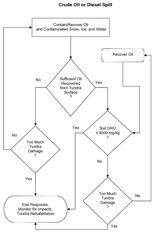
Figure 3a. Generalized example of a decision tree to help develop a site-specific treatment strategy for crude oil or diesel spills.
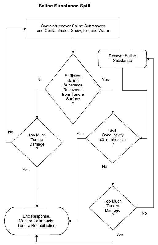
Figure 3b. Generalized example of a decision tree to help develop a site-specific treatment strategy for saline substance spills.
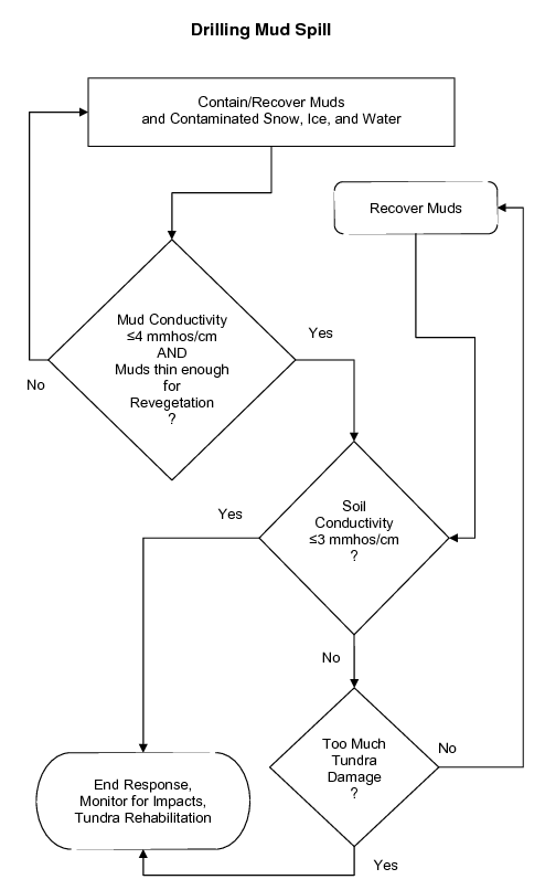
Figure 3c. Generalized example of a decision tree to help develop a site-specific treatment strategy for drilling mud spills.
Tactic P-2: Understanding the Tundra Environment

Figure 4. Boundaries of the arctic coastal plain and arctic foothills on Alaska’s North Slope (based on Wahrhaftig 1965)
An understanding of the tundra environment is critical when choosing tactics and strategies for treating a spill. Following is an overview of four generalized tundra types and their characteristics. Although this discussion focuses on Alaska’s North Slope (arctic tundra), the planning, treatment, and monitoring, tactics in this manual also apply to tundra environments elsewhere in Alaska, including alpine tundra.
What is tundra?
Tundra is a Russian word translated as “treeless plain” (Merriam-Webster definition of Tundra) or “marshy plain” (Billings 1974). Tundra in this manual is used to describe ecosystems where the indigenous plant cover consists of low herbaceous, dwarf shrub, or lichen vegetation in places which have summers too cold to allow tree growth. Tundra includes the circumpolar treeless region north (and south) of the latitudinal treeline and the less extensive mountain landscapes above altitudinal treeline (Murray 1978).

Figure 5. Example of ice wedge (approximately 3-ft wide) and permafrost beneath a thawed layer of soil (active layer)
Alaska’s North Slope stretches from the crest of the Brooks Range north to the Arctic Ocean (Fig. 4). The Arctic Coastal Plain area is flat and wet with abundant oriented thaw lakes. In contrast, the Arctic Foothills Area is a broad expanse of valleys and hills. The climate is characterized by extreme winter cold, strong winds, and brief summers (about 90 days [June–August]) when the air temperature is generally cool and there is relatively little precipitation. The soil at depth remains perennially frozen (permafrost) but an “active layer” of surface soil, varying in depth from a few inches to a few feet, thaws each summer and refreezes each winter (Fig. 5). The rooting depth of plants and most of the activity of soil microbes are limited by the depth of the active layer (i.e., thaw depth). Although annual precipitation is low, surface water is abundant, because permafrost limits water infiltration and movement. Tundra vegetation consists of low-growing plants including mosses, lichens, grasses, sedges, and dwarf shrubs. Compared to most other environments, relatively few plant species have adapted to the extreme conditions of the tundra (Fig. 6). Soils develop slowly in the Arctic, because the cold climate and short growing season limit the decay of dead plant matter.
What are the types of tundra?
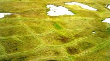
Figure 6. Aerial photo of polygonal features in tundra. The boundaries between poloygons indicate the locations of ice wedges such as the close-up in Figure 5
This manual classifies tundra into four types: aquatic, wet, moist, and dry (Figs. 7–10). These generalized types are based on a hierarchical tundra vegetation classification scheme developed by Walker (1983, 1985). They occur in three major geographic provinces on the North Slope of Alaska: 1) the coastal plain, 2) the foothills, and 3) the mountains of the Brooks Range, as well as on the Seward Peninsula.
Wet tundra is the most common type on the coastal plain, due to the low topographic relief and the presence of a shallow, saturated active layer. Patterned ground features (i.e., polygons bounded by ice wedges, Fig. 6) are abundant. In the foothills province, moist tundra predominates on slopes, wet tundra in low areas, and dry tundra on exposed hilltops and ridges. Patterned ground is less common here. In the Brooks Range and above treeline in other mountain ranges in Alaska, dry tundra predominates. High shrub thickets develop on floodplains, in sheltered areas or where snow accumulates and protects plants from harsh winter winds. In the braided channels of active floodplains, the soil surface is frequently barren. Figure 11 illustrates topographic features and subsurface conditions associated with a few of the common plant community types on the North Slope.
Aquatic Tundra
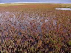
Figure 7. Aquatic tundra
- Occurrence: Frequently forms marshes along the margins of ponds, lakes and streams, and may form a mosaic with wet tundra.
- Common Plants: Arctic pendant grass (Arctophila fulva), water sedge (Carex aquatilis), and mare’s tail (hippuris spp.).
- Soils: Thick layer of aquatic sediments and peat.
- Active Layer: Deep at maximum thaw (late summer). A thaw basin of unfrozen soil may be present in the vicinity of ponds, lakes, and streams.
Wet Tundra
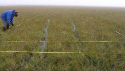
Figure 8. Wet tundra
- Occurrence: Where shallow (< 1 ft) surface water persists through all or most of the growing season, in troughs, low centers of polygons, and in wet areas within drained lake basins. Wet tundra is the most common tundra type on the coastal plain. May form a mosaic with moist tundra where the soil is saturated but without standing water.
- Common Plants: Water sedge (Carex aquatilis), tall cottongrass (Eriophorum angustifolium), Fisher’s tundra grass (Dupontia fisheri), and arctic pendant grass (Arctophila fulva).
- Soils: A mat of roots and organic matter approximately 1 ft thick, underlain by mineral soils. The organic soil layer and rooting zone are thicker in wet tundra than in dry or moist tundra. Ponds and standing water are common within wet tundra areas, and soil pore spaces are saturated with water during the growing season.
- Active Layer: Moderate to deep at maximum thaw. The high thermal conductivity of water may melt the top of permafrost in the summer despite the insulating effects of the highly organic root mat, especially if the surface has been physically disturbed. This active layer is often about 1 foot (12 inches) in depth (Fig. 12), but may extend to about 3 feet below the tundra surface in wet tundra.
Moist Tundra
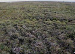
Figure 9. Moist (tussock) tundra
- Occurrence: Usually where the soil is saturated in a portion of the active layer throughout the growing season, but standing water is absent or present for only a part of the growing season. Areas of moist tundra on the North Slope include the slopes of hills, on high-centered polygons, and the rims of low-centered polygons.
- Common Plants: Sedges (Carex aquatilis and C. bigelowii), cottongrasses (Eriophorum angustifolium and E. scheuzeri), and dwarf shrubs including willows (Salix spp.), birch (Betula spp.) and mountain-avens (Dryas spp.). Tussock tundra is a common type of moist tundra on the North Slope, especially in the foothills. It is dominated by tussock cottongrass (Eriophorum vaginatum), dwarf shrubs, mosses, and lichens.
- Soils: A dense, compressed mat of roots and organic matter overlies mineral soils.
- Active Layer: Relatively thin due to the dense insulating organic mat and moderate soil moisture content.
Dry Tundra
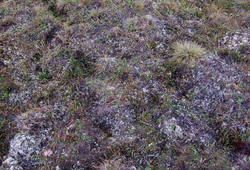
Figure 10. Dry tundra
- Occurrence: Where good drainage creates relatively dry soil conditions throughout the growing season. On the slopes of mountain ranges, on ridges and hilltops in foothills, stabilized sand dunes, pingos, and other well-drained sites on the coastal plain.
- Common Plants: Dwarf shrubs including birch, willow, mountain-avens, blueberry and cranberry (Vaccinium spp.), Labrador tea (Ledum palustre ssp. decumbens), crowberry (Empetrum nigrum), arctic bell-heather (Cassiope tetragona), and bearberry (Arctostaphylos spp.), along with lichens, mosses, and grasses.
- Soils: Thin root mat and low organic matter content compared to soils of moist and wet tundra. Ample drainage reduces the ability of the thin root mat to hold moisture.
- Active Layer: The active layer in dry tundra is usually comparable to wet and moist tundra, but can be as deep as 3 feet.
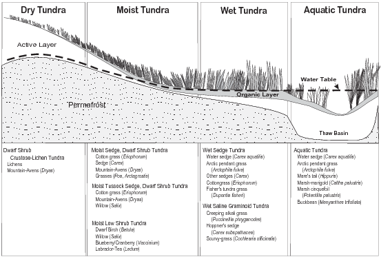
Figure 11. Characteristic plant communities and associated species are listed for the four tundra types (based on Walker et al. 1980)
Sensitivity to Disturbance
Tundra environments can be especially sensitive to disturbance for several reasons:
- Permafrost
- Short growing season
- Extreme winter wind and cold temperatures
Tundra vegetation and soil insulate the permafrost layer from the sun and warm surface air during the growing season. Actively growing plants cool the soil by drawing water from the soil (evapotranspiration). Surface disturbances can interfere with these processes, causing ice in the soil to melt and resulting in subsidence (thermokarst). Drainage patterns are affected by subsidence, leading to further changes in topography and hydrology. For example, thermokarst in dry or moist tundra can lead to formation of wet or aquatic tundra, but thermokarst in wet tundra also can lead to drier conditions.
Difficulty Treating Spills
Spills on tundra can be difficult to treat for several reasons:
- Short summer season, when most treatments are easier to implement.
- Low temperatures limit the rate of microbial breakdown of hydrocarbons (biodegradation).
- Remote locations present practical challenges for cleanup efforts.
- Patterned ground features or tussocks make treatment more complicated.
- Soils and vegetation may be physically damaged, which can impede achievement of the treatment goals.
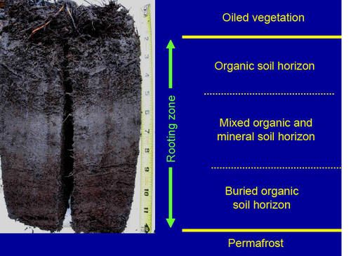
Figure 12. Typical soil profile in wet tundra
Tactic P-3: Understanding the Effects of Spills on the Tundra
This tactic provides a brief description of some potential spill substances and their expected effects on tundra vegetation and soils. Information was summarized recently in Tundra Spill Cleanup and Remediation Tactics: A Study of Historic Spills and Literature (Behr-Andres 2001).
This planning tactic focuses on substances that are produced, extracted, or used in the production or extraction of oil and gas in Alaska’s arctic oilfields. Substances of concern include crude oil, diesel fuel, gasoline, Therminol™, glycol (ethylene and propylene), methanol, drilling fluids and muds, produced water, seawater, and acids. Spills within the arctic oilfields commonly involve the release of more than one substance; a typical example would be a combined release of produced (saline) water and crude oil.
In tundra areas outside the oilfields, spills of diesel, gasoline, and sewage are the main potential concerns. Spills of other substances would typically be small, and would likely require the development of spill-specific treatment strategies.
In general, a rapid response to a spill will mini-mize the spread of contaminants across the tundra surface and the vertical migration of contaminants into the soil. Containment and product recovery generally must be completed as soon as possible after the spill. In winter, snow and ice help to contain contaminants and to minimize soil penetration.
Crude Oil
Crude oil contains thousands of organic and a few inorganic compounds, including natural gas, liquefied petroleum oils, resins, and asphaltenes. Hydrocarbons, which are composed only of carbon and hydrogen atoms, are the most abundant components of crude oil. Other components include sulfur, oxygen, nitrogen, and a variety of metals which are bound to organic compounds or exist as inorganic salts.
Crude oil can damage or kill plants in several ways. The light fractions are more volatile and consist of short-chain alkanes (i.e., saturates or paraffins) and aromatic (one or more rings of benzene) hydrocarbons. Light fractions cause the most severe damage by penetrating and destroying plant tissues. Heavier fractions of crude oil can coat the surface of the leaves and interfere with the exchange of oxygen and carbon dioxide, which is necessary for plant survival.
Crude oil can damage vegetation indirectly by creating hydrophobic (unwettable) soil conditions, thereby reducing the supply of water to plant roots. Crude oil can also displace the air from pore spaces in dry or moist tundra, causing the soil to become anoxic and acutely toxic to plants and soil microbes.
Several factors influence the toxic and physical effects of crude oil on tundra vegetation, including the volume spilled (Table 1), the presence of snow or surface water, weathering, and soil properties. For example, if oil is perched on top of frozen or water-saturated soils, the more toxic aromatic fractions may evaporate without penetrating the soil. This is especially important for sedges and grasses because the buds that sprout new tissue lie below ground and can escape the most damaging components of crude oil if the oil remains on the surface (Walker et al. 1978). In general, shrubs, mosses and forbs have been shown to be more sensitive to crude oil than grasses and sedges (Walker et al. 1978; Jorgenson and Cater 1992a). Dry tundra is considered to be more susceptible to crude oil damage than moist or wet tundra, because the aromatic fractions can be carried into the soil before they evaporate, damaging or killing roots and buds.
Table 1. Conversions for oiling rates, surface thickness, and soil concentrations of crude
| Surface Oiling Rate | Surface Thickness | Percent Oil in Soil by Volume | Percent Oil by Dry Weight (soil bulk density = 0.4 g/cm3) | Parts per Million (ppm; mg/kg); Dry Weight Basis | |||||||
|---|---|---|---|---|---|---|---|---|---|---|---|
| L / m2 | Quarts | Gal / acre | bbl / acre | mm | Inches | Soil Oiling Depth (cm) | Soil Oiling Depth (cm) | Soil Oiling Depth (cm) | |||
| 10 | 5 | 10 | 5 | 10 | 5 | ||||||
| 10 | 2-1/4 | 10,691 | 255 | 10 | 3/8 | 10 | 20 | 22 | 44 | 220,000 | 440,000 |
| 5 | 1 | 5,346 | 127 | 5 | 3/16 | 5 | 10 | 11 | 22 | 110,000 | 220,000 |
| 1 | 1/4 | 1,069 | 25 | 1 | 1/16 | 1 | 2 | 2.2 | 4.4 | 22,000 | 44,000 |
| 0.1 | -- | 107 | 3 | 0.1 | -- | 0.1 | 0.2 | 0.22 | 0.44 | 2,200 | 4,400 |
Diesel Fuel
Diesel fuel, also referred to as “middle distillate,” is refined from crude oil and is composed primarily of hydrocarbons with 8 to 21 carbon atoms per molecule. Refined petroleum products, including diesel, are generally more toxic to plants, microbes, and animals than is crude oil. When diesel is spilled, the volatile components (aromatic hydrocarbons such as benzene) often evaporate, changing the chemical composition of the remaining fuel. Diesel will eventually mix with water in the soil or on the tundra surface, allowing it to migrate into the surface soil and root mat. Compounds such as polynuclear aromatic hydrocarbons (PAHs) may adsorb to fine particles in tundra soil. Once adsorbed, PAHs may persist for a long time because they are unavailable to soil microbes that degrade hydrocarbons. However, the adsorption of PAH molecules by soil can reduce phytotoxicity by reducing the amount of hydrocarbons in contact with plant roots.
Direct exposure to diesel will kill leaves, and can kill the entire plant if roots and buds are also exposed. As explained above (see Crude Oil), spills to dry or moist tundra are potentially more damaging than similar spills to wet tundra. This is partly due to protective effects of water-saturated soil, and partly to characteristics of the dominant plant growth forms in the different tundra types.
Gasoline
Gasoline is a highly volatile and flammable refined petroleum product that spreads rapidly to a thin sheen on water or wet soil. Evaporation rates are very high, as gasoline contains a larger percentage of volatile aromatic compounds than either diesel or crude oil.
Like diesel, gasoline is generally more damaging to vegetation, microbes, and animals than is crude oil. Direct contact of plant leaves, buds or roots with gasoline will often kill the entire plant. In wet tundra, saturated soil may initially provide some protection from gasoline spills, as explained above (Crude Oil). However, like diesel, gasoline will eventually mix with water, allowing it to migrate into the surface soil and root mat. Moist and dry tundra are highly susceptible to the effects of gasoline for the same reasons they are readily damaged by diesel spills—rapid penetration of the soil and trapping of the aromatic fractions in the rooting zone, where they can be toxic to vegetation. Many of the harmful aromatic fractions of gasoline, however, may evaporate before penetrating tundra soils.
Saline Waters and Substances
Seawater and brine are used on the North Slope as part of enhanced oil recovery processes and are transported by pipeline and truck. Produced water is generally separated from the oil stream and reinjected at well heads. The salt in seawater, brine, and produced water consists mainly of sodium chloride, which can negatively affect plant growth and survival at relatively low concentrations. These effects may be persistent since, unlike hydrocarbons, salts are not broken down by chemical or biological processes in soil. Low precipitation and hydrologic gradients typical of the North Slope may prevent salts from being flushed from soils as quickly as they would be in many other areas. Soil amendments (e.g., gypsum) may ameliorate the negative effects of salt spills (Tactic TR-13).
High levels of salts in soil increase the osmotic potential of soil water, making water uptake difficult for most tundra plants. Depending on salt concentrations, salt-affected vegetation may wilt, become discolored, drop leaves, or die within hours or days of contact with foliage or roots (Barker 1985). Jorgenson et al. (1987) found that damage to tundra vegetation was absent at soil salinity levels below 2–3 mmhos/cm, moderate between 2–3 and 6–10 mmhos/cm, and severe above 6–10 mmhos/cm. Simmons et al. (1983) made controlled releases of seawater to tundra at 8 sites in the Prudhoe Bay, Alaska area. They found that wet tundra was affected much less than moist and dry tundra, reflecting different physiological tolerances of the dominant species, as well as dilution of salts in soils with high water content.
Many spills involve mixtures of crude oil and saline water, and initial cleanup efforts usually emphasize recovery of the crude oil. However, salts can also be harmful to vegetation at relatively low concentrations, and the effects are usually longer lasting since salts are not broken down in soil. Some recent spill responses have focused on the simultaneous recovery of both contaminants.
Drilling Mud and Fluids
Drilling muds and fluids are generally variable and complex mixtures designed to meet oil-well drilling needs. Many current mixtures are water-based, and often contain bentonite clay (barium sulfate), and saline substances (e.g., potassium chloride). Mixtures may also be oil-based, which often include denatured diesel fuel (i.e., mineral oil). Drilling mud spills often include varying amounts of crude oil and saline water. Drilling muds and fluids can affect tundra plants by changing soil salinity and alkalinity, as well as smothering due to burial.
Synthetic Fluids
Methanol. Also known as wood alcohol or methyl alcohol, methanol is a highly flammable, volatile solvent used in oilfield operations. Methanol is a clear, colorless liquid with a pungent odor, and is completely soluble in water. Methanol evaporates quickly from soil and water when exposed to air. This chemical is highly toxic to wildlife, but its toxicity to plants is not well known.
Glycols. Ethylene and propylene glycol are synthetic liquids that mix with water. They are used as antifreeze for vehicles, in heating systems, and in industrial applications. Glycols are clear, odorless liquids that mix completely with water and have low vapor pressures. Abiotic transformations in soil or water are not significant except that glycols are subject to photo-oxidation by the sun. Little information is available on the toxicity of glycols to plants. Ethylene glycol is highly toxic to animals, so initial responses to spills of this compound should focus on wildlife protection, followed by containment and recovery.
Therminol. An insoluble organic liquid commonly used as a heat transfer fluid for pump stations and well houses. In its raw form, it is a clear yellow liquid with a mild hydrocarbon odor and is viscous even at below-freezing temperatures. Little is known about the environmental toxicity of Therminol, but test results suggest that it is resistant to biodegradation (Solutia MSDS).
Tactic P-4: Minimizing Physical Damage to Tundra
Cleanup of a spill on tundra almost inevitably results in some degree of physical damage, caused by one or more of the following:
- Repeatedly walking over the same area when the active layer of soil is thawed.
- Driving vehicles or heavy equipment on tundra when the active layer of soil is thawed.
- Repeatedly driving vehicles or heavy equipment over the same area at any time.
- Excavating (Tactic CR-13), trimming (Tactic CR-12) or trenching (Tactic CR-9).
- Using high-pressure or hot water to flood (Tactic CR-7) or flush (Tactic CR-8).
- Injuring the root mat while burning (Tactic CR-10) or scraping (Tactic CR-12), especially when the soil is very dry.
Vehicle and foot traffic over thawed tundra can destroy vegetation and permanently compress organic soils. These ruts or compressed areas may change site drainage patterns, causing drying of some areas and inundation of others. Damage to vegetation and compression or removal of organic soils may reduce their insulating effects on the tundra surface, which can cause underlying permafrost to thaw and the soil to subside (thermokarst). Thermokarst can change dry or moist tundra to wet or aquatic tundra by creating depressions that fill with water. Once the thermal regime and drainage of an area are disturbed, the changes may be essentially permanent.
Traffic on wet tundra during summer can result in a disturbance that is highly visible, because vegetation and soil are compressed and the tracks fill with water. However, the wetland sedges that dominate wet tundra vegetation often recover rapidly from mild to moderate disturbance. The main concern with summer travel on wet tundra is the relatively high potential for vehicles to become stuck, which may result in more substantial damage that requires treatment. Traffic on dry tundra may appear to cause less damage because there are fewer plants and no standing water, but the physical effects are likely to persist for longer than in wet tundra.
In order to minimize physical damage to tundra during spill cleanup:
- Limit foot and vehicle travel on tundra as much as possible.
- Avoid following the same path repeatedly (enter and exit the site from different paths, if possible).
- Use existing roads (gravel, peat, or snow) as much as possible.
- Use snow ramps to access tundra from gravel roads and pads.
- Use existing gravel and ice pads for staging where possible.
- Use plywood or interconnecting rig mats as boardwalks or working platforms for light equipment (Fig. 13).
- Use snowshoes when repeated trips on foot cannot be avoided.
- Limit use of invasive treatment tactics (e.g. trimming) as much as possible.
- Replace displaced tundra sod back into original divot, or transplant tundra sod (Tactic TR-10) to replace soil and vegetation that have been removed.
- Restore natural contours and drainage by filling excavations.
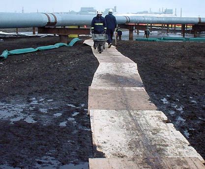
Figure 13. Using plywood to avoid trampling
Considerations and Limitations
- Boardwalks should be light enough to be moved manually, so they can be easily moved around the site as needed (Fig. 14).
- If treatment tactics require heavy equipment, tundra travel permits, proper road construction, or use of rig mats may be required (Tactic P-5).
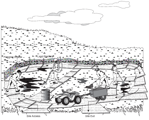
Figure 14. Typical layout of plywood and equipment
Tactic P-5: Tundra Travel
Tundra travel permits may be required for vehicles traveling off-road in many areas. Industry operators often have tundra travel permits in place. If no permits are in place, work through the Unified Command and/or contact the appropriate landowners and agencies to identify the plans or permits that are required.
For state-owned land on the North Slope, the policy of the Alaska Department of Natural Resources, Division of Land (DNR) requires a permit for any vehicle traveling on tundra during any season. Permits are issued for either summer tundra travel (July 15 until freeze-up), winter tundra travel (freeze-up until breakup), or both. No off-road travel is permitted during the period from breakup until July 15 except for true emergencies.
Winter Tundra Travel
Spill responders should follow the guidelines provided by DNR for tundra travel. Because cleanup efforts may require the use of heavy equipment when these conditions are not met, this manual provides additional information to help responders avoid causing too much tundra damage (see Tactics P-4 and AM-3).
In Alaska, tundra is generally open to off-road travel when the ground is frozen to a depth of 12 inches and when there is at least 6 inches of snow on the ground. DNR has developed recommendations for winter tundra travel based on experimental data that separate tundra into two distinct geographical areas (Coastal and Foothill Areas, see Figure 1 in Tactic P-1). The regulations may be changed to allow travel on tundra when soil temperatures are colder than or equal to –5 degrees C (23.1 degrees F) at a depth of 12 inches (30 cm) below the surface, and when at least 6 inches (15 cm) of snow is present in the Coastal Area and at least 9 inches (23 cm) of cover snow is present in the Foothills Area. The date of tundra opening on the North Slope has ranged from as early as November 4 to as late as January 25. Once the tundra has been opened for winter travel, there are no restrictions on the types of vehicle that may operate on the tundra. In years of limited snowfall, tundra travel may be opened conditionally, with the stipulation that vehicles are restricted to areas where sufficient snow has drifted to prevent damage to the tundra vegetation.
Winter tundra travel on the North Slope is closed when it appears that the snow has become too soft and/or too limited in extent to allow travel without damaging vegetation. Operators are then given 72 hours notice to move vehicles and other equipment off the tundra.
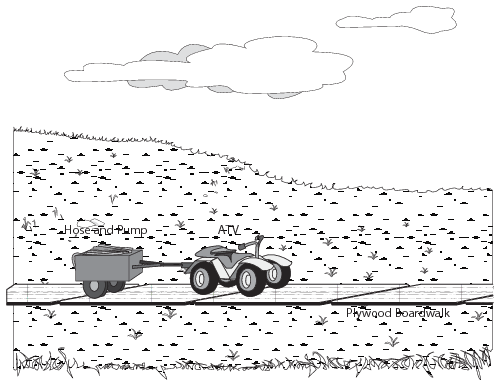
Figure 15. Using 4-wheel all-terrain vehicle on plywood
Summer Tundra Travel
See DNR guidelines for complete listing of travel requirements. The following vehicles have been tested and approved by DNR for summer tundra travel:
- Argo 8 I/C with smooth tracks
- Roller-driven Rolligon
- Haggland Bearcat with smooth track configuration
- Tucker-Terra Sno-Cat model 1600 with smooth track configuration
- Airboats (for use in spill drills and exercises only)
In addition, DNR can issue a permit approving summer use of 4-wheel all-terrain vehicles on boardwalks placed on the tundra (Fig. 15) (Tactic P-4). Use of heavy equipment or airboats to respond to a spill on tundra during summer months is permitted on a case-by-case basis.
Vehicles are tested to determine whether they can operate on the tundra during summer without causing extensive tundra damage (Fig. 16). Approvals are only for the configuration tested; for example, a vehicle tested with a payload of 1,000 pounds is limited to that payload when operating on the tundra. A vehicle tested and approved with smooth tracks would require retesting before it could be operated with cleats or wheels.
The following stipulations apply to all summer tundra vehicles operating on state land:
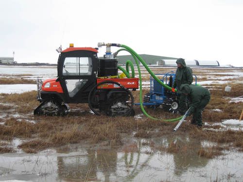
Figure 16. Vehicle designed for tundra travel in summer
- Operations are restricted to drier areas whenever possible.
- Crossing deep water or vegetation with more than 2–3 inches of standing water shall be avoided if at all possible.
- Crossing ponds or lakes or the wetlands immediately bordering these areas is not authorized.
- Minimum-radius turns with sharp articulations shall be avoided where possible.
- Multiple passes over the same area shall be kept to a minimum.
- All operators shall be made familiar with tundra vegetation types to ensure compliance with these stipulations.
- The state reserves the right to limit, restrict, or require retesting of vehicles at any time.
- Incidents of damage to the vegetative mat and follow-up corrective actions that have occurred shall be reported to the Division of Land within 72 hours of occurrence.
- Vehicles cannot carry more payload than was carried during the certification test.
Considerations and Limitations
- Other regulations may apply for travel on lands managed by government organizations (e.g., North Slope Borough) and federal agencies (e.g., Bureau of Land Management).
Tactic CR-1: Sorbents
Sorbents can be used to pick up spill residuals from tundra and to prevent movement of hydrocarbons into clean areas. Use sorbents if water is not available for flooding or flushing, or if the topography of the site prevents the effective use of booms to contain flooding or flushing water. The choice of which sorbent material to use depends on the substance spilled, season, and availability. The use of sorbents can be labor-intensive compared to other cleanup techniques. Deploying and recovering sorbent material can result in physical damage to tundra; this risk must be carefully weighed against the benefits of removing the residuals. Some examples of sorbent materials include:
- Polypropylene sorbents (pads and boom material) (Figs. 17, 18, and 19)
- Snow (Figs. 20 and 21)
- Granular sorbents (e.g., sawdust or commercially available products)
- Straw
- Pom Poms
Use polypropylene sorbents on crude oil or oil-based substances directly on the tundra surface, or on heavy sheen on standing water in wet or moist tundra or impoundments. A polypropylene sorbent boom can be fixed in position with stakes or fencing to collect floating product in aquatic or wet tundra, or to prevent floating product from moving off site. Sorbent wringers can be used to extend the life of fibrous polypropylene sorbents.
Snow is an effective and readily available sorbent for recovering residues from the tundra surface in winter. Apply snow, recover the snow/residue mixture using hand tools or heavy equipment (Tactic CR-3) and remove for disposal. Other adsorptive materials like granular sorbents or straw may be used if snow is not available.
Considerations and Limitations
- Polypropylene sorbents are not effective for non-hydrocarbon spills (e.g. drilling muds or produced water), and are much less effective after surfactants (Tactic CR-8) have been applied.
- Polypropylene sorbents work well on fresh crude, light refined oils, and thick petroleum sheens, but are only partially effective on solidified or weathered oil, highly viscous oil, very thin sheens, or emulsified oil.
- Snow, granular sorbents, and straw are not effective for spill residue floating on water.
- The use of sorbents generates a large amount of waste that requires proper disposal.
- Prolonged use of sorbents on dry tundra may be counterproductive because tundra damage may result.
- This tactic has been adapted from Tactics R-2, R-8 and R-9 in the Alaska Clean Seas Technical Manual.
Equipment, Materials, and Personnel
NOTE: Personnel typically work in pairs for sorbent deployment and recovery.
- Appropriate sorbent material - to collect spill residue.
- Stakes or fencing - to secure sorbent boom to create a sorbent fence.
- Shovels, rakes, pitchforks - for application and removal of sorbents.
- Plastic bags or disposal drums - for collection of saturated sorbents.
- Vehicle approved for tundra travel (optional) - to collect and transport saturated sorbent materials.
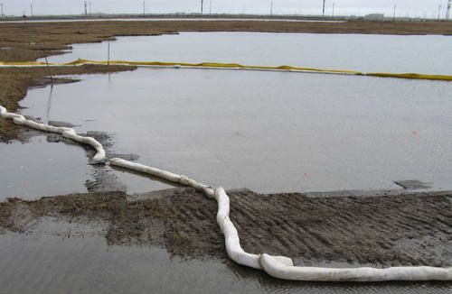
Figure 17. Sausage booms for containing floating oil
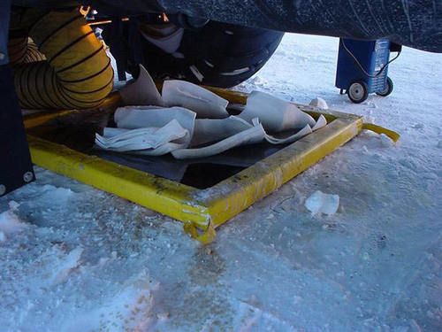
Figure 18. Sorbent sheets used to recover oil
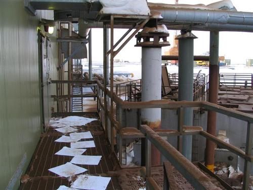
Figure 19. Sorbent used to prevent spread of contaminants
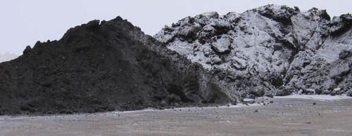
Figure 20. Snow after being used as a sorbent
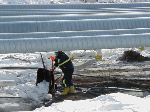
Figure 21. Using snow as a sorbent
Tactic CR-2: Manual Removal
Manual removal of spill residue may include collecting spilled substances or contaminated debris with rakes, mops, pitchforks, trowels, shovels (Fig. 22), buckets, portable vacuum systems (Figs. 23 and 24) , and/or sorbent materials (Tactic CR-1). Contaminated material can be placed directly in plastic bags or drums for transfer. If the containers are to be carried to temporary storage areas, their weight should be limited to what one person can safely carry.
A rubber squeegee (or similar tool) can be used to gently compress and agitate the tundra surface, to squeeze contaminants out of pore spaces of the organic layer. Compression and agitation may be used in conjunction with flooding (Tactic CR-7) or flushing (Tactic CR-8) to enhance recovery of spill residue.
During manual removal activities, avoid damaging plant roots and uncontaminated vegetation. The potential for physical damage to the tundra must be carefully weighed against the benefits of removing additional spill residuals. Workers should be provided with clear guidelines that will allow them to decide when to discontinue manual removal.
Considerations and Limitations
- Take proper precautions to protect tundra from foot and vehicle traffic (Tactic P-4).
- Manual removal is not useful for some non-hydrocarbon spills such as seawater.
- This tactic has been adapted from Tactics R-2 and SH-2 in the Alaska Clean Seas Technical Manual.
Equipment, Materials, and Personnel
- Rake (1 per worker) – recovery.
- Mop (1 per worker) – recovery.
- Squeegee (1 worker) – agitation.
- Portable vacuum system (1 operator) – to recover spilled material.
- Portable generator (1 operator) – to power vacuum system.
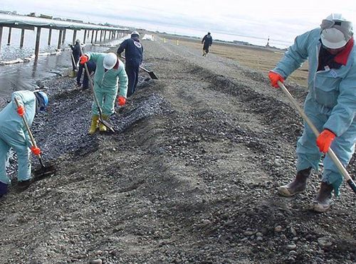
Figure 22. Shoveling contaminated gravel
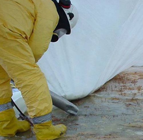
Figure 23. Vacuuming liquid contaminant
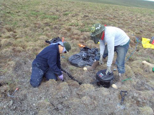
Figure 24. Vacuuming drilling mud
Tactic CR-3: Snow Management
Moving snow onto or off a site may be useful for a variety of reasons:
- Snow can be used as a sorbent to recover spill residue (Tactic CR-1).
- Snow can be placed on a site to reduce desiccation (i.e., freeze-drying) during winter, prevent early sprouting in spring, and/or provide water to plants during the growing season (Tactic TR-4).
- Snow can be removed from a site so that contaminated vegetation and soil may be scraped (Tactic CR-12).
- Snow can be removed from a site in spring to allow an earlier start to the growing season (Tactic TR-2).
Snow can be handled with heavy equipment or by hand. Snow can be scraped into piles by a dozer (Figs. 25 and 26), and transferred to dump trucks using a front-end loader. A loader with an extension (e.g., push blade in Fig. 27) may be needed to push snow beneath pipes. Manual handling of snow is recommended when working in congested areas, on uneven ground where heavy equipment is likely to scrape high spots, or when there is insufficient snow cover to prevent heavy equipment from damaging the tundra. If the snow is contaminated with spill residue, it must be stored in an approved containment area and proper disposal must be arranged. If the snow is not contaminated, it may be stockpiled nearby or used to build a snow berm to isolate the site during spring snow melt (Tactic CR-3).
Move the snow into piles or windrows using brooms, shovels, or heavy equipment. Transfer the piles to garbage cans, totes, or similar containers. Once a container is full, use a snow machine or Argo to transfer it to a stockpile or a truck on a pad or road (Fig. 28).
Considerations and Limitations
- Use of vehicles on tundra must comply with applicable tundra travel policies (Tactic P-5).
- Topographic relief (e.g., tussocks, patterned ground) may preclude use of heavy equipment, because high spots are easily scraped.
- Use a spotter for each piece of heavy equipment when working in areas with above-ground pipes or other obstacles.
- Avoid stockpiling clean snow on contaminated areas. Snow piles will persist into the growing season and inhibit vegetation recovery.
- Install a snow fence to prevent snow from accumulating on the site.
- A snow fence can also be used to encourage accumulation of snow on the site.
- Maintain sufficient snow coverage around the site to prevent damage by supporting operations.
- This tactic has been adapted from Tactics R-2 and R-3 in the Alaska Clean Seas Technical Manual.
Equipment, Materials, and Personnel
- Snow shovels and brooms (1 worker per tool) – manual snow removal.
- Garbage cans or totes (1 or more workers per container, depending on weight of container) – to carry snow to trailer.
- Snowmachine or Argo with trailer (1 operator) – to transport collected snow or containers.
- Challenger (1 operator) – to scrape snow into piles for removal.
- Front-end loader with bucket (1 operator) – to transfer snow to dump truck.
- Push blade attachment for loader (1 operator) – to allow heavy equipment to push snow beneath above-ground pipes.
- Dump truck (1 operator) – to transport snow for storage or disposal.
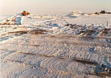
Figure 25. Removing snow in spring
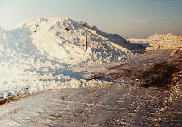
Figure 26. Snow removed to excavate contaminated soil
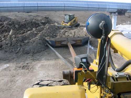
Figure 27. Loader extension pushing material
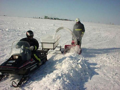
Figure 28. Removing snow piles
Tactic CR-4: Drainage Protection
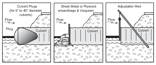
Figure 29. Blocking of culverts
Drainage protection is used to keep contaminants from moving off site. It may be needed during spring breakup and summer when contaminants are mobilized and water is flowing through culverts, or while using treatment tactics such as flooding (Tactic CR-7) or flushing (Tactic CR-8).
A culvert can be blocked using sheet metal, plywood barriers, inflatable culvert plugs, or adjustable weirs (Fig. 29). Plywood or sandbags can also be used as culvert blocks, but require more labor to install. Place blocking materials over the upstream end of the culvert. Plastic sheeting over the outside of the block will decrease the likelihood of water leaking through the block. Block water flow through a culvert only if the impounded water will not threaten the road or raise water levels sufficiently so that additional tundra becomes contaminated.
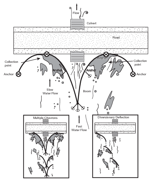
Figure 30. Boom deployed upstream of culvert
If blocking a culvert is likely to damage a road or flood uncontaminated areas, a boom may be deployed in a chevron or diversionary configuration, allowing water to flow while deflecting oil from the mouth of the culvert to collection sites along the road (Fig. 30). This technique is especially useful when there is sheet flow of water across the frozen tundra. Boom systems will not provide drainage protection from water-soluble contaminants.
Considerations and Limitations
- Culverts should be unblocked when spill response is complete, to avoid impounding water and possibly washing out the road.
- This tactic has been adapted from Tactics C-2 and C-3 in the Alaska Clean Seas Technical Manual.
Equipment, Materials, and Personnel
- Boom (2 workers) – to deflect floating contaminants from culvert.
- Anchor system (2 workers) – to secure boom system.
- Visqueen (2 workers) – to prevent seepage through permeable culvert blocks.
- Inflatable culvert plug (2 workers) – to block culvert.
- Air compressor (1 worker) – to inflate culvert plug.
- Sheet metal or plywood barriers (2 workers) – to block culvert.
- Sandbags (2 workers) – to block culvert.
- Flatbed truck (1 worker) – to transport sandbags.
- Front-end loader (1 worker) – to unload sandbags.
Tactic CR-5: Land Barriers
Land barriers can be used for the following purposes:
- Contain and limit further spreading of contaminants (CR-4).
- Contain water used during flooding (Tactic CR-7) or flushing (CR-8).
- Augment a natural depression or a trench to act as a containment area for recovery (Tactic CR-9).
- Prevent water from flowing onto a site during draining (Tactic TR-1).
Land barriers can be constructed using sand bags (Fig. 31), shore sealing boom (Fig. 32), large diameter hoses filled with water, sheet piling (Fig. 33), and mixtures of snow and ice (Fig. 34). Berms of tundra soil and gravel may also be used, but these are less desirable because they create additional disturbances. The type of barrier chosen depends on the site topography, tundra type, and treatment strategy. When flooding an area, it must be enclosed completely so that the water level can be raised above the ground surface and the floating hydrocarbons recovered. When using a barrier to prevent contaminants from spreading, form the barrier materials into a horseshoe shape to collect contaminants downslope of the flow. To capture flooding or flushing water for recovery, use barriers to augment a natural depression or a trench and to direct water toward the containment area.
Water-soluble substances can infiltrate soil and move horizontally below the surface in all tundra types, thus subsurface barriers (e.g., sheet piling) may be needed to prevent subsurface movement (Fig. 33).
Considerations and Limitations
- Hydrocarbons will tend to float on wet and moist tundra, but will infiltrate soil in dry tundra.
- Use of vehicles on tundra must comply with applicable tundra travel policies (Tactic P-5).
- Proper disposal of the materials used to construct barriers should be taken into account.
- Shore seal boom is effective if frozen in place, but reinforcement with sandbags or ice berms is needed on both sides where the boom crosses troughs or other low spots.
- Walk on land barriers when possible to avoid damaging tundra.
- All land barrier techniques (except sheet piling) described in this tactic have been adapted from Tactic C-4 in the Alaska Clean Seas Technical Manual.
Equipment, Materials, and Personnel
- Appropriate boom material (2 to 5 workers, depending on site) – to construct land barriers.
- Backhoe (1 operator) – to build gravel or tundra berm.
- Bobcat loader (1 operator) – to push snow into berm.
- Water source (1 operator) – to turn snow berms into ice berms.
- Front-end loader with bucket (1 operator) – to move gravel or sand bags.
- Floating pump and blower (2 operators) – to fill shore seal boom with air/water.
- Visqueen or similar heavy plastic sheeting – to line gravel or tundra berms.
- Sledge hammer – to install sheet piling.
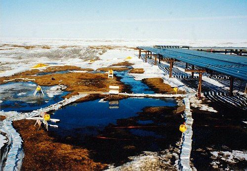
Figure 31. Sand bags
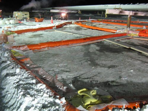
Figure 32. Shore sealing boom
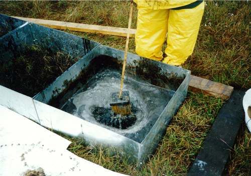
Figure 33. Sheet piling
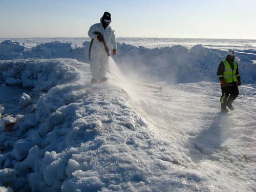
Figure 34. Snow and ice berm
Tactic CR-6: Recovery with Skimmers and Pumps
Use skimmers (Figs. 35–37) to recover oil floating on the water surface. A variety of skimmers are available that are designed for different situations. The choice of skimmer to use is dependent on factors such as the thickness of the floating oil layer, the depth of water, the degree of weathering of the oil, and whether the oil has been treated with surfactant. Skimmers are most effective when the floating oil is concentrated in a thick layer. Position the skimmer in the area of heaviest concentration of spill residue. A skimmer requires a power pack; a pump with suction and discharge hoses and fittings; and a storage container for recovered product.
At a spill site adjacent to a road or pad, a vacuum truck can be used to drain an area (Tactic TR-1) or to recover pooled spills (Figs. 38—39), flood water (Tactic CR-7) or flush water (Tactic CR-8) from natural depressions, land barrier containment (Tactic CR-5), or trenches (Tactic CR-9). The effective range of a vacuum truck is approximately 200 feet when removing viscous liquids such as crude oil, and 400 feet when removing diesel or water. A Super Sucker can be used for direct suction to remove liquids combined with solids (e.g., gravel) that vacuum trucks cannot handle (Fig. 40).
Submersible pumps or trash pumps can be used to pump areas that are not accessible by vacuum truck or Super Sucker. Submerge the pump or intake hose in the deepest area of an impoundment. Make sure the pump intake or hose end is fitted with a screen to prevent vegetation from clogging the intake hose.
Considerations and Limitations
- Identify the disposal method or facility to be used and estimate the volume of liquid requiring disposal before skimming or pumping fluids from a spill site.
- Identify the flash points of fluids being recovered.
- Consider ambient temperature when selecting length and diameter of hoses.
- This tactic has been adapted from Tactics R-6 and R-8 in the Alaska Clean Seas Technical Manual.
Equipment, Materials, and Personnel
- Any shallow draft skimmer (e.g., rope mop or Manta ray) (usually 2 operators to deploy and maintain) - to remove floating product.
- Manta ray skimmer (1 or 2 operators to deploy and maintain) - to remove floating product.
- Power pack - to provide a power source for skimmer.
- Pumps and hose (2 operators to deploy and maintain) - to suction product from site.
- Tank or tanker truck (1 operator).
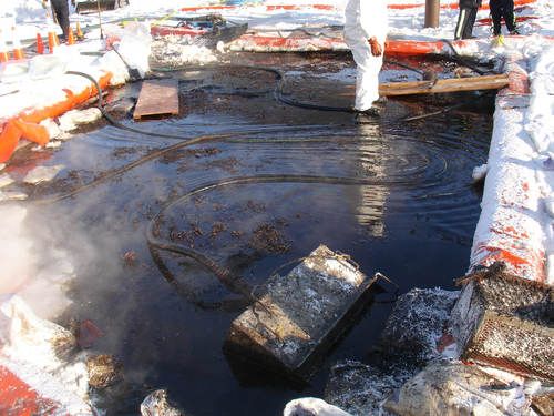
Figure 35. Skimming floating oil with slurper skimmer
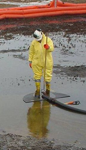
Figure 36. Manta ray skimmer
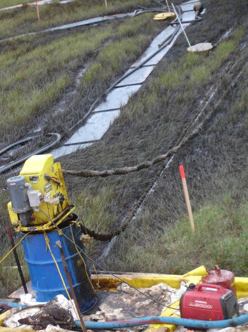
Figure 37. Rope mop in wet sedge tundra
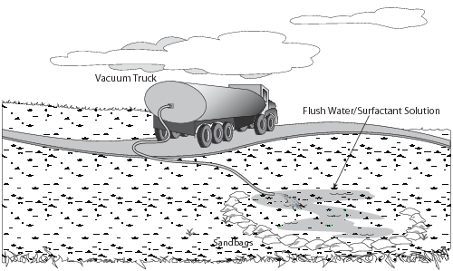
Figure 39. Vacuum truck
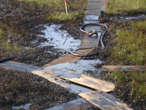
Figure 38. Vacuum hose recovering oil from low spot
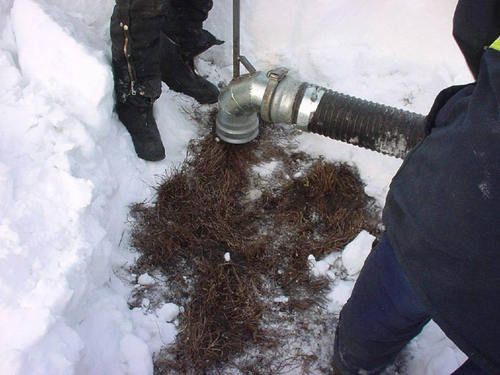
Figure 40. Super sucker
Tactic CR-7: Flooding
The use of flooding with clean water depends on the nature of the spilled substance:
- Crude Oil and Diesel: Flooding raises or maintains the water level on the tundra surface, reducing the contact of oil with vegetation and making the use of skimmers (Tactic CR-6) or sorbents (Tactic CR-1) more effective (Fig. 41). In dry tundra, flooding also fills pore spaces in the root mat or soil with water, reducing the amount of oil that can infiltrate. Repeated flooding, followed by removal of the floating oil, can greatly increase recovery of hydrocarbons.
- Water-Soluble Substances (salts, methanol, glycol): Flooding reduces toxicity by diluting the contaminants. The diluted contaminants can then be recovered by pumping (Tactic CR-6). Flooding and pumping can be repeated as needed.
Flooding and flushing (Tactic CR-8) are similar approaches. The potential for erosion is the primary factor to assess when choosing which of these two tactics to use. Use flooding when the potential for erosion is moderate or higher, and use flushing when the potential for erosion is low.
Most sites should be divided into several cells that are small enough to manage efficiently (Fig. 42). Water pressure and flow rate should be kept low to minimize erosion; using a Manta Ray skimmer in reverse to diffuse the input of water works well (Fig. 43). Move the input hose periodically to prevent erosion. Water may be pumped from a nearby tundra pond or creek, or transported to the site using trucks with clean tanks. Do not use seawater or produced water to flood tundra vegetation. Land barriers (Tactic CR-5) are needed to contain water on site (Fig. 44), especially during snowmelt (Fig. 45). In summer, flood with cold or warm water. Hotter water will be needed during winter to allow recovery before the water freezes. Snow melters can generate very hot water (up to 180°F), and may be the best choice during winter at remote sites with no road access, if the volume of water produced is sufficient. In winter, water can be hauled to the site in heated or insulated tanks.
Surfactants reduce adhesion of crude oil and fuels to vegetation by increasing the ability of water to mix with hydrocarbons. Flooding with surfactants is appropriate for final cleanup of hydrocarbon spills after most of the spilled product has been removed (Fig. 44). Surfactants can be mixed with water in tanks, or added to the stream of water flowing out of the input hoses. Dawn™ detergent is the recommended surfactant because it is not toxic to soil microbes at concentrations used during flushing (Jorgenson and Cater 1992a); it is commonly used for cleaning oiled wildlife because of its effectiveness and low toxicity (Hemenway 1990); and it is readily available. Apply Dawn™ at a 0.1% (by volume) concentration. Surfactants also decrease the ability of sorbent pads, booms, and skimmers to recover hydrocarbons, and should only be used after these methods are no longer needed.
Avoid thawing of frozen soil to the extent possible, to minimize infiltration of contaminants into the rooting zone, and exposure of dormant vegetation to freeze-thaw cycles.
Considerations and Limitations
- Maintaining a constant water level is important to prevent exposure of previously unaffected vegetation on higher areas (e.g., polygon rims) to floating or dissolved contaminants, as well as preventing repeated contact of oil with vegetation within the flooded area.
- Create a current in flood water or set-up petroleum collection downwind to remove floating hydrocarbons immediately.
- Surfactants decrease the ability of sorbent pads, booms, and skimmers to recover hydrocarbons, and are generally used during the final flooding, after most of the spilled product has been recovered.
- Surfactants can create enough suds to make operations difficult; add soap carefully.
- Surfactants are not effective for removing substances that mix with water (e.g., salts, glycol).
- Insulated water tanks lose heat at the rate of approximately 10°F every 12 hours.
- Ensure that land barriers (Tactic CR-5) are strong enough to contain water in the flooded area, and that the seal with the tundra surface will not leak.
- If ice berms are used as the land barrier, hot water may cause the berm to fail.
- Ensure water is free of hydrocarbons and salts before using it to flood tundra.
- Assess concentrations of contaminants in floodwater periodically using field screening techniques.
- Flood as few times as possible, to minimize physical damage to vegetation.
- Flooding is feasible during winter, but precautions for worker safety are necessary. Flooding may not be practical at extremely cold temperatures.
- Protect tundra being flooded by walking on plywood boardwalks, sandbags, rig mats, etc.
- Flooding may also be used to irrigate (Tactic TR-4) a site during the growing season.
- This tactic has been adapted from Tactic R-4 in the Alaska Clean Seas Technical Manual.
Equipment, Materials, and Personnel
- Water truck or upright tank (1 operator) - to provide water source.
- Pumps and suction and discharge hose (1 to 2 operators each) – to pump water to and from site.
- Land barriers (Tactic CR-5) (number of people needed is site-dependent) – to contain water on site and to provide collection point.
- Clean water (not seawater or produced water).
- Plywood, sandbags or rig mats – to prevent trampling.
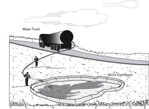
Figure 41. Typical site layout
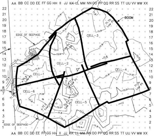
Figure 42. Treatment cells, grid layout, topography
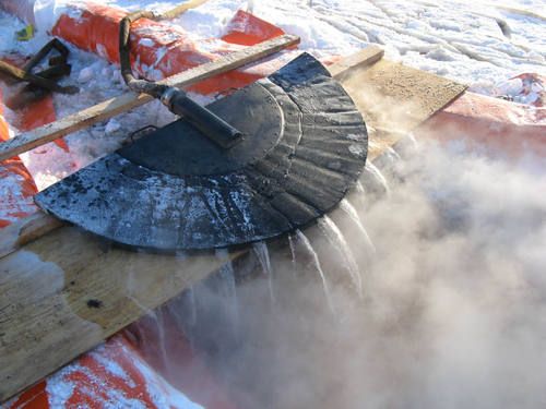
Figure 43. Manta ray skimmer used as inlet hose to prevent erosion
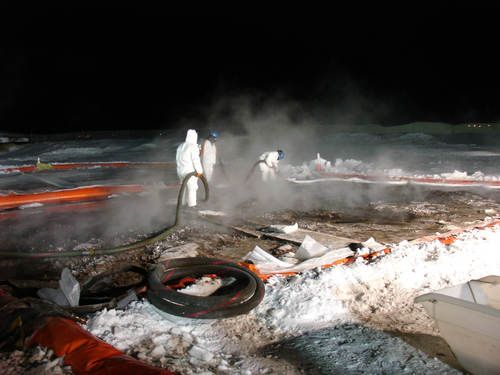
Figure 44. Flooding tundra in winter
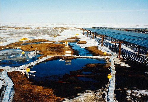
Figure 45. Land barriers to contain snow melt within cells
Tactic CR-8: Flushing
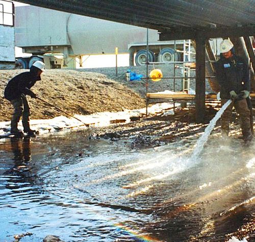
Figure 46. Flushing ice to mobilize oil
Flushing with clean water is used to mobilize oil from ice (Fig. 46), vegetation, and the tundra surface. If necessary, gently agitate and compress the tundra surface with a rubber squeegee (Tactic CR-2) while directing water flow with the discharge hose. Agitation is most useful in wet tundra where the organic mat is relatively thick and resistant to erosion.
Flushing typically adds and removes water continuously. Keep water pressure and flow rate low enough to minimize erosion. Flush toward a collection area, such as a natural depression or a trench (Tactic CR-9) lined with plastic sheeting, where the oil can be recovered with direct suction (Tactic CR-6) or sorbents (CR-1). A land barrier (Tactic CR-5) is typically needed to contain fluids.
Flushing and flooding (Tactic CR-7) are similar approaches. The potential for erosion is the primary factor to assess when choosing which of these two tactics to use. Use flushing when the potential for erosion is low; use flooding when the potential for erosion is moderate or higher.
Water may be obtained from a nearby tundra pond or creek, or transported to the site in trucks with cleaned tanks. Do not use seawater or produced water to flush tundra vegetation. Flushing water must be contained using land barriers (Tactic CR-5). In summer, flush with cold or warm water. Hotter water will be needed during winter to allow recovery before the water freezes. In winter, water can be hauled to the site in heated or insulated tanks. Snow melters can generate very hot water (up to 180°F), and may be the best choice during winter at remote sites with no road access, if the volume of water produced is sufficient.
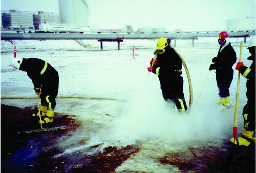
Figure 47. Flushing tundra with surfactants
Surfactants reduce adhesion of crude oil and fuels to vegetation by increasing the ability of water to mix with hydrocarbons. Flushing with surfactants is appropriate for final cleanup of hydrocarbon spills after most of the spilled product has been removed (Fig. 47). Dawn™ detergent is the recommended surfactant because it is not toxic to soil microbes at concentrations used during flushing (Jorgenson and Cater 1992a); it is commonly used for cleaning oiled wildlife because of its effectiveness and low toxicity (Hemenway 1990); and it is readily available. Apply Dawn™ at a 0.1% (by volume) concentration. Surfactants also decrease the ability of sorbent pads, booms, and skimmers to recover hydrocarbons, and should only be used after these methods are no longer needed.
Surfactants can be mixed with water in tanks, or added to the stream of water flowing out of the input hoses. Most sites should be divided into several cells that are small enough to manage efficiently (Fig. 48).
Avoid thawing of frozen soil to the extent possible, to minimize infiltration of contaminants into the rooting zone, and exposure of dormant vegetation to freeze-thaw cycles.
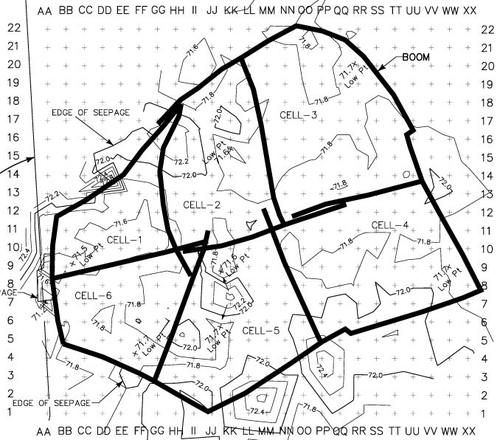
Figure 48. Site divided into 6 cells for treatment
Considerations and Limitations
- Flush as few times as possible, to minimize physical damage to vegetation.
- Move the input hose periodically to minimize erosion.
- Surfactants are not effective for removing substances that mix with water (e.g., salts, glycol).
- Insulated water tanks lose heat at the rate of approximately 10°F every 12 hours.
- Ensure that land barriers (Tactic CR-5) are strong enough to contain water in the area being flushed, and that the seal with the tundra surface will not leak.
- If ice berms are used as the land barrier, hot water may cause the berm to fail.
- Skimmers and sorbents will not be effective after surfactants have been applied to the site.
- Protect tundra being flushed by walking on plywood boardwalks, sandbags, rig mats, etc.
- Ensure water is free of hydrocarbons and salts before using it to flush tundra.
- Flushing is feasible during winter, but precautions for worker safety are necessary. Flushing may not be practical at extremely cold temperatures.
- This tactic has been adapted from Tactic R-4 in the Alaska Clean Seas Technical Manual.
Equipment, Materials, and Personnel
- Water truck (1 operator), tank, tundra pond or stream – to provide water source.
- Clean water (not seawater or produced water)
- Surfactant (Dawn™ detergent) – to enhance recovery of spill residue.
- Trash pump (1 to 2 operators each) – to pump water to and from site.
- Suction hose (1 operator) – to take up water from water source.
- Discharge hose (3- to 6-inch) with adjustable valve (1 operator) – to discharge water on site.
- Mop, squeegee (1 operator) – to agitate and gently compress tundra mat to release spill residue.
- Land barriers (Tactic CR-3) (number of people needed is site-dependent) – to contain water on site and to provide collection point.
- Plywood, sandbags or rig mats – to prevent trampling.
Tactic CR-9: Trenching
Trenching is used to intercept the flow of a spilled substance, to divert a spilled substance around a sensitive area, or to capture and recover water used during flooding and flushing (Figs. 49 and 50). Examining the sidewall of a trench can help determine if spilled substances are moving below the ground surface (Fig. 51). Dig trenches by hand or using a trencher attached to a skid loader, tractor, or other type of heavy equipment.
Dig a trench or series of trenches at right angles to the flow, angled slightly downhill to avoid excessive pooling. Place the excavated material on the downhill side of the trenches. Line the sides and bottoms of trenches with plastic sheeting. A trench can be flooded with water to inhibit contaminant penetration and to promote flow toward a recovery device.
Digging trenches in tundra should be considered a last resort, if no other tactic is available to divert or capture water or contaminants. Do not excavate trenches in an area where the excavation will cause more damage than benefit. Excavating trenches in permafrost terrain will disrupt the thermal regime and cause thermal erosion (thermokarst). It may be necessary to backfill trenches (Tactic TR-12) to reestablish a stable thermal regime, and revegetation may be needed to meet rehabilitation goals for the site.
Considerations and Limitations
- Vehicle use on tundra must comply with applicable tundra travel policies (Tactic P-5).
- The Bobcat trimmer should be used for trenching only if no other options exist. It can cut a maximum depth of about 4 inches per cut; a trench deeper than 8 inches will be as wide as the Bobcat.
- It may be necessary to survey spot elevations before trenching, to ensure that fluids flow into the trenches.
- A permit may be needed from the landowner before trenching.
- Trenching in tundra should be considered a last resort. Trenching may lead to further disturbance if a natural stream, river, or swale intercepts the path of the trench.
- This tactic has been adapted from Tactics R-7 and C-12 in the Alaska Clean Seas Technical Manual.
Equipment, Materials, and Personnel
- Shovels (1 worker per tool) – to hand dig trench.
- Skid loader, or tractor with trenching attachment (1 operator) – to dig trench.
- Visqueen or similar heavy plastic sheeting – to line trench.
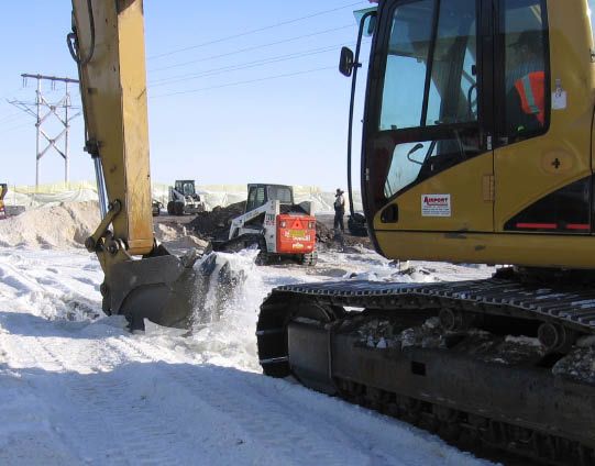
Figure 49. Excavating trench in ice
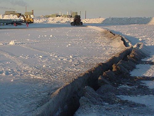
Figure 50. Excavated trench
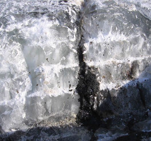
Figure 51. Oil exposed in sidewall of trench
Tactic CR-10: Burning Contaminated Vegetation
Burning is used primarily to volatilize and oxidize residual contaminants from vegetation after other tactics have been used to recover most of the spilled substance. This tactic is especially useful for light coatings on leaves of sedges and grasses that are elevated above the tundra surface (Figs. 52–53). Burning was first tested on the North Slope in the late 1970’s (Fig. 54). This tactic is not appropriate for removing pooled product from the ground surface. The relatively large amount of heat required to burn pooled product could 1) cause vertical migration of the substance into the rooting zone and 2) induce thermokarst in the underlying tundra soil.
Typically, one worker uses a metal rake to orient oiled leaves and stems more or less vertically. A second worker uses a weed burner, which consists of a flame nozzle, hosing, and a propane tank. The flame nozzle is held just above the contaminated vegetation until the vegetation is burned down to stubble. Burn residue can be recovered with hand tools, but the benefit of recovery should be carefully weighed against the potential for causing additional physical damage to the tundra.
The risk of damage from burning is relatively modest in moist and wet tundra dominated by sedges. Much of the biomass of these plants, including the buds from which new leaves sprout, is deep enough to be protected from the heat of the fire. Use additional caution in drier tundra where shrubs, mosses and lichens are abundant, as these growth forms have little or no ability to sprout from belowground parts.
Considerations and Limitations
- Burning vegetation contaminated with weathered oil or fuel may produce a residue that is difficult to clean up.
- Burning as soon as possible after a spill will increase the likelihood of complete combustion because fewer of the volatile components (e.g., benzene) in the spilled substance will have evaporated.
- Follow proper safety procedures and use personal protective equipment, as required.
- Burning should be considered only when there is minimal risk that the fire will spread to unaffected areas. This consideration is especially important when dry sedge and grass leaves (i.e., dead plant litter) are present.
- Permission must be obtained from the Alaska Department of Environmental Conservation and potentially from the U.S. Environmental Protection Agency before burning tundra vegetation.
- This tactic has been adapted from Tactics B-2 and SH-10 in the Alaska Clean Seas Technical Manual.
Equipment, Materials, and Personnel
- Metal rake (1 worker) – to orient oily vegetation.
- Weed burner with propane tank (1 operator) – to ignite spilled residue and vegetation.
- Fire extinguisher (1 operator) – to suppress unwanted fire.
- Fans (1 operator) – to increase burning efficiency (optional, if conditions are appropriate).
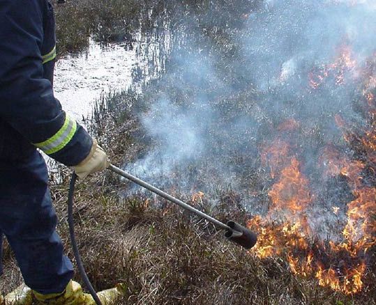
Figure 52. Propane torch burning contaminted vegetation
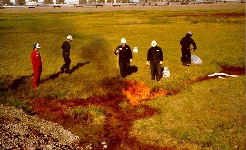
Figure 53. Burning a thin layer of surface contamination
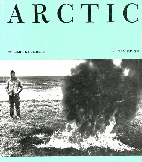
Figure 54. 1979 edition of Arctic
Tactic CR-11: Removing Contaminated Vegetation
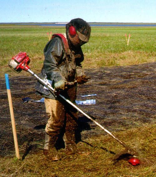
Figure 55. Trimming vegetation
Remove contaminated vegetation to prevent remobilization of spill residuals, and to promote recovery of the remaining live plant tissues. Only remove above ground vegetation that is dying or dead (Fig. 55). Avoid damaging plant roots to maximize sprouting of new shoots and leaves. Collect the trimmed material into bags by hand, raking, or shoveling, and remove from the site for proper disposal. Minimize contact between contaminated and uncontaminated vegetation.
General Considerations and Limitations
- Place plywood on the ground to minimize trampling and shearing of roots.
- This tactic is less likely to cause physical damage when the ground is frozen and vegetation is dormant.
- This tactic is labor-intensive and may not be suitable for large sites where site access would cause physical damage to areas unaffected by the spill.
Equipment, Materials, and Personnel
Note: Personnel typically work in pairs when cutting and trimming vegetation.
- String or line trimmer (1 operator) – to cut grasses and sedges (non-woody vegetation) on larger sites.
- Scissors or knives (1 worker) – to cut vegetation on smaller sites.
- Hand clippers, pruners, or brush cutter (1 worker) – to cut woody plant stems.
- Rakes (1 worker) – to collect clipped and cut plant materials.
- Bags for collecting cut leaves.
- Cans for collecting woody plants.
Tactic CR-12: Mechanical Removal: Scraping, Trimming, and Brushing
Use scraping, trimming, and brushing to recover contaminants on the tundra surface while leaving as much soil as possible, to preserve live buds, roots, and rhizomes (Figs. 56—60). Mechanical removal can be used while the ground is frozen or partially thawed. Trimmers are especially effective for breaking up contaminated ice and packed snow. Mechanical removal can also be effective in spring when air temperatures are still well below freezing, but solar heating is sufficient to thaw the surface soil after snow has been removed. Contaminants can be easier to see when soil is partially thawed (Figs. 61 and 62), and a spotter can direct the operator, but the depth of removal must be controlled carefully to minimize tundra damage. This tactic works best for viscous substances, such as crude oil, which tend to remain on the tundra surface rather than penetrating into the soil.
Damage from scraping and trimming can be severe in moist and dry tundra, because the plants’ rooting systems are often within 1 inch of the tundra surface. In contrast, much of the rooting systems of plants in wet tundra are deeper than 1 inch below the tundra surface, and are more likely to be left in place after mechanical removal.
Use a mechanical brush to clear the area of snow (Tactic CR-3) and expose the tundra surface (Fig. 63). Trimmed ice and snow can be removed with a Super Sucker vacuum truck or by methods described in the snow removal tactic (Tactic CR-3). Adjust the blade or trimmer to remove a thin layer of soil. Transfer contaminated material to dump trucks and transport to appropriate waste disposal facilities.
Considerations and Limitations
- Identify the disposal method or facility to be used and estimate the volume requiring disposal before mechanical removal begins.
- Most or all lichens and mosses will be removed by scraping and trimming.
- Scraping and trimming may be impractical for areas with small-scale topographical relief (e.g., tussock tundra, patterned ground).
- Avoid stockpiling clean snow on contaminated areas. Snow piles will persist into the growing season and inhibit vegetation recovery.
- Use of vehicles and heavy equipment on tundra must comply with applicable tundra travel policies (Tactic P-5).
- Trimming should be employed as soon as possible following the gross removal of the non-frozen spilled substance, to limit vertical movement of contamination.
- This tactic is not intended to remove pooled product from the ground surface.
- To avoid damage to the root mat, trimming should be limited to the tops of the plant shoots.
- Method of trimming, including equipment, materials and personnel, will be determined by the size and topography of the site.
Equipment, Materials, and Personnel
- Trimmer (one operator) – to trim the spill-affected surface ice (size of trimmer will be dependent on size of spill and topography).
- Grader/dozer/Bobcat (1 operator) – to scrape snow and contaminated surface vegetation.
- Spotter - to visually identify boundaries where scraping or trimming is needed.
- Front-end loader and/or Super Sucker (one to two operators) – to pick up trimmed or scraped ice and snow.
- Brooms, rakes, and shovels (one worker per tool) – to sweep up loose ice and snow not picked up by previous methods.
- Front-end loader (1 operator) – to transfer scraped or trimmed material into end dumps.
- Dump truck (1 operator) – to transfer scraped or trimmed material to disposal site.
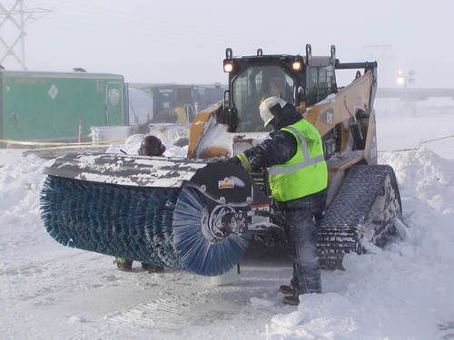
Figure 63. Mechanical brush for clearing snow
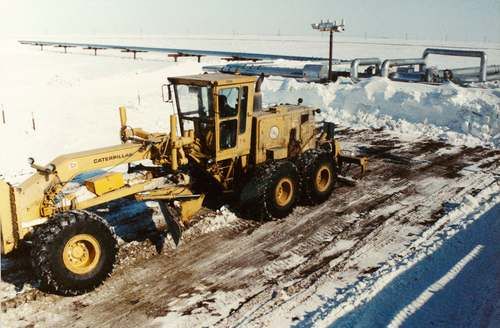
Figure 56. Scraping soil saturated with oil
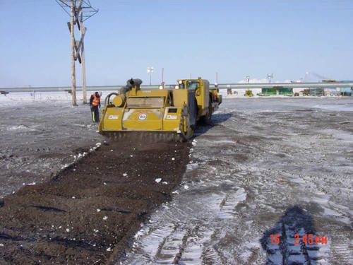
Figure 57. Seventy-two-inch trimmer
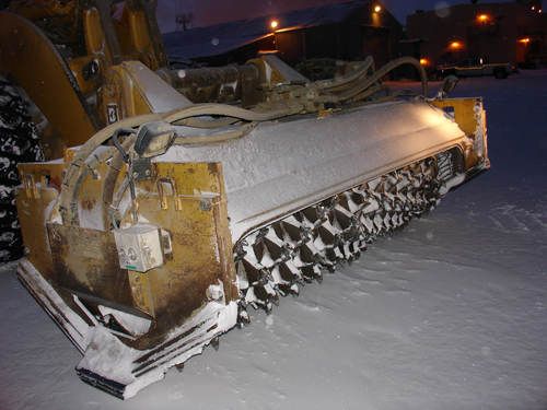
Figure 58. Forty-two-inch trimmer
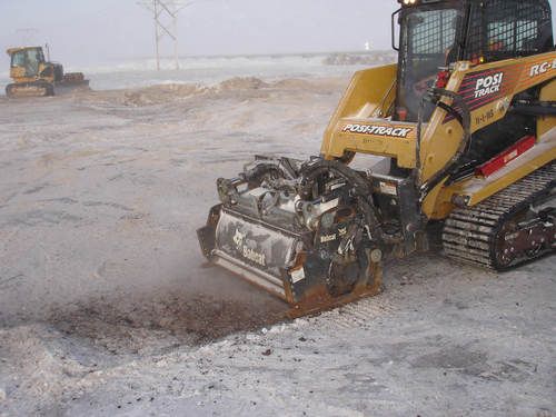
Figure 59. Twenty-four-inch trimmer
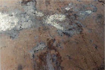
Figure 61. Oily spots in scraped tundra
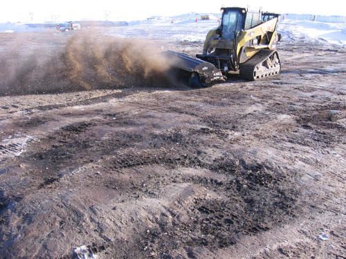
Figure 60. Rotating brush
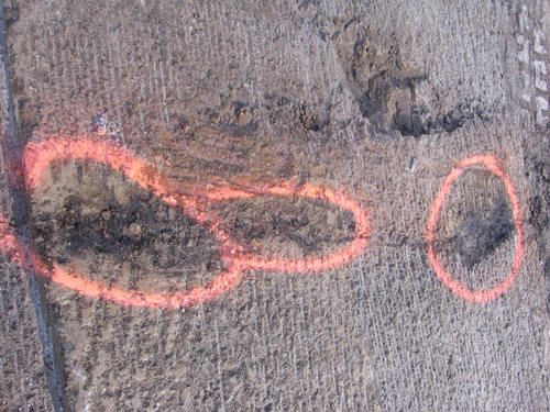
Figure 62. Oily spots in trimmed tundra
Tactic CR-13: Excavation for Offsite Disposal
Excavation of tundra soil may be necessary when treatment goals include the rapid and complete removal of spill residuals. Excavation should be considered if contaminant levels are high enough to be toxic to plants, if the entire organic mat is saturated with contaminants, or when other treatment options have been deemed inadequate for achieving the treatment goals.
Dozers, backhoes (Fig. 64), trimmers (Figs. 65–66), and jackhammers (Fig. 67) can be used to excavate the organic mat and underlying mineral soils. Contaminated soil is typically removed from the site for treatment or disposal.
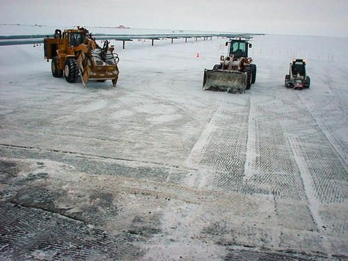
Figure 66. Site after excavation with trimmer
The depth of infiltration by contaminants determines the depth of soil that should be removed. It may be feasible to remove only the organic mat, before the spilled material infiltrates down to mineral soil. Minimize the volume of soil excavated by using a spotter to direct the operator to contaminated areas. For example, at many sites, contaminants tend to flow into a network of polygon troughs, leaving higher areas relatively unaffected. However, soil testing (Tactic AM-4) is often needed to identify areas to excavate, because even highly visible substances (e.g., crude oil) are difficult to see under certain conditions, especially during winter with artificial lighting. Consider removing only “hot spots” and leaving as much tundra as possible intact to prevent excessive damage to the tundra (see Tactic AM-3).
In most cases the excavated area must be backfilled (Tactic TR-12) to minimize the risk of thermokarst (Fig. 68). Therefore, a source of approved replacement material must be identified before excavation begins. Excavation may create a tundra environment suitable for some plants but not others. Backfilling may not be necessary if creation of aquatic habitat is an acceptable rehabilitation option.
Considerations and Limitations
- Remove soil only to the depth to which contaminants have infiltrated.
- Identify a source of approved fill material before beginning excavation.
- Ensure backfill has suitable properties (e.g., particle size, relative amounts of gravel, sand, and silt).
- Allow for settling after backfilling in order to maintain proper surface grade relative to the surrounding tundra.
- Monitoring surface elevation over time may be necessary to document site stability.
- Consider disposal options and required approvals before using this tactic.
- On-site sampling of contaminated soil can expedite the excavation process.
Equipment, Materials, and Personnel
- Backhoe or trimmer (1 operator) – to excavate contaminated soil or ice.
- Front-end loader (1 operator per loader) – to transport excavated material.
- Dump truck (1 operator) – to transport contaminated material to disposal site.
- Polyethylene sheeting – lining for stockpiles.
- Spotter – to guide excavation of visibly contaminated soil.
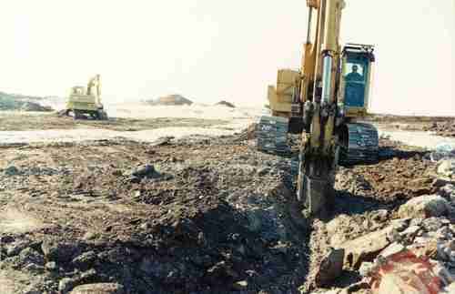
Figure 64. Backhoe excavating contaminated soil
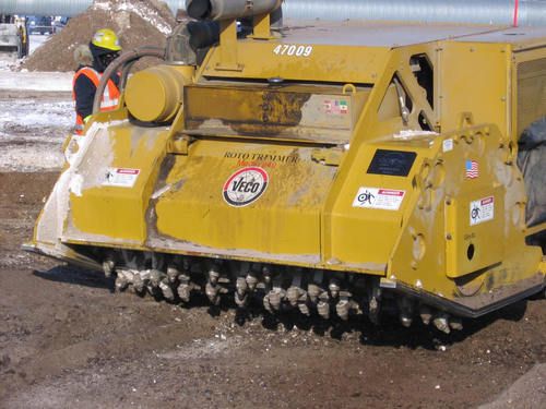
Figure 65. Trimmer excavating contaminated soil
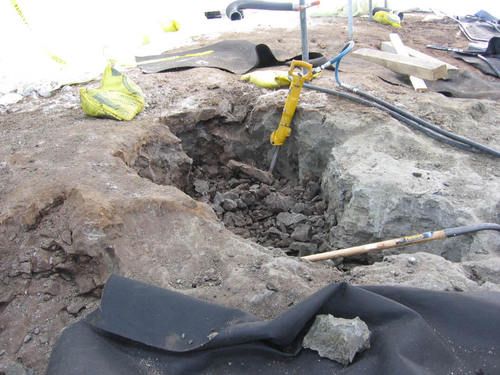
Figure 67. Excavating frozen soil with jackhammer
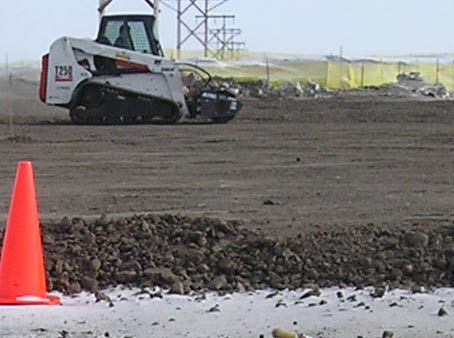
Figure 68. Edge of backfilled area after excavation
Tactic TR-1: Draining and Dewatering
Flooded tundra soils are generally anoxic (lacking oxygen) because the soil pore spaces are full of water. Use draining and dewatering to aerate the soil by lowering the water table and promoting the infiltration of oxygen (Fig. 69). Aeration enhances the ability of soil microbes to degrade residual hydrocarbons (Tactic TR-5). Use this tactic after spill residuals have been removed to the chosen extent.
Drain the site by blocking incoming water with land barriers (Tactic CR-5) and pumping water from the area (Tactic CR-4). Use or enhance topographical relief to create collecting points for pumps or vacuum trucks. Trenches or sumps (Tactic CR-6) may also be needed.
Draining is not recommended when floating product is present; product may be introduced into soil pore spaces or contact vegetation when water level is drawn down. It will usually be unnecessary and impractical to drain aquatic tundra, except for small water bodies. Do not completely dewater tundra if the technique will result in contaminants contacting sediments.
Place suction hoses in all low areas where water collects (Fig. 70); suction may be required at numerous locations within a site. If the site cannot be reached by vacuum truck and hose, all-terrain vehicles (ATVs) may be used to bring in small tanks or drums to collect the water (appropriate tundra travel permits required). It may be necessary to test the collected water for contamination before draining. Proper approvals must be obtained for discharge or disposal of contaminated water from spill sites.
Considerations and Limitations
- Test water for contamination and consider disposal options and required approvals before using this tactic.
- Tundra must be thawed to dewater soil pore spaces.
Equipment, Materials, and Personnel
- Water truck (optional) (1 operator).
- Pumps (1 operator).
- Hoses (1 to 2 operators) – common sizes are 2- and 3-inch diameter.
- Land barriers (Tactic CR-5).
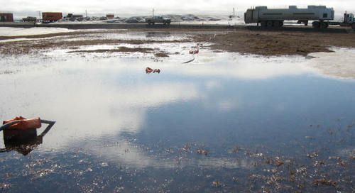
Figure 69. Vacuum truck dewatering site
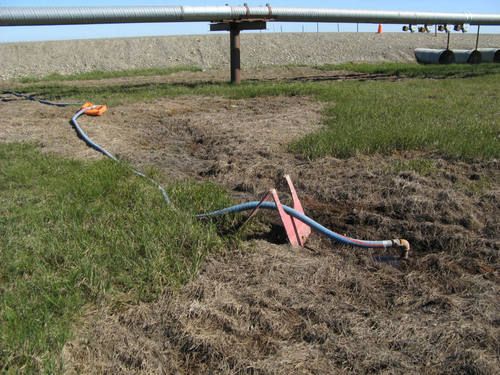
Figure 70. Natural low spot used for dewatering
Tactic TR-2: Extending the Growing Season
Extending the period during which soil is thawed increases the amount of microbial degradation of hydrocarbons that can occur in a given year. Extending the growing season can also enhance plant growth, but plant mortality can result if sprouting begins too early in the spring while air temperatures are still well below freezing.
The following techniques can be used to extend the growing season:
Early spring snow removal to degrade hydrocarbons: Scraping snow off the tundra surface (Tactic CR-3) in April or May will initiate soil thawing and promote the onset of microbial activity 30 to 60 days earlier than under natural conditions (Figs. 71–72). Also, solar radiation levels in the Arctic typically are highest during this period, and exposure to sunlight will promote the photochemical degradation of hydrocarbons remaining on the ground surface. Snow can be removed by hand from small areas or with heavy equipment as long as the ground is frozen. Leave enough snow in place to prevent physical damage to the tundra surface.
Early spring snow removal to enhance vegetation growth: Scraping most of the snow off the tundra surface (Tactic CR-3) will speed soil thawing and promote vegetation growth (Fig. 73). If snow is removed too early, however, plants will sprout while air temperatures are still well below freezing, which will likely result in plant mortality. Snow removal is most beneficial to plants at sites covered by large drifts or by snow piles resulting from routine snow removal. If not removed, these areas of deep snow can delay soil thawing until late June or July, strongly limiting plant growth. Snow can be removed by hand from small areas or with heavy equipment as long as the ground is frozen. Leave enough snow in place to prevent physical damage to the tundra surface.
Snow fencing: Snow fencing will keep snowdrifts off sites and speed spring thawing, thus promoting soil microbial activity and plant growth (Figs. 74 and 75). Snow fencing should be approximately 4–8 feet high, and must be placed PPRendicular to the prevailing winds and secured with guy wires. Place one fence within several feet of the site, and stagger 2 or 3 additional rows of fencing behind it at 30- to 50-foot intervals. The length of the fences depends on the size of the site.
Tenting: A tent can be constructed to create a snow-free, heated environment to enhance microbial activity (Fig. 76). Tenting is not necessary for enhancing plant growth. This tactic can be used during spring, summer, and fall. A low tent made with clear polyethylene sheeting and lumber or metal frame can be inflated, heated, and ventilated with a forced-air heater unit.
Considerations and Limitations
- When enhancing microbial activity and plant growth are dual goals, consider the trade-off between promoting early onset of microbial activity and the risk of plant mortality if sprouting occurs too early in the season.
- Snow removal in early spring may limit the water supply on site early in the growing season. Irrigation (Tactic TR-4) may be required during the growing season to compensate.
- Snow fencing left in place for more than a few growing seasons may change the plant communities impacted by the drifts, by repeatedly delaying the onset of the growing season, and by creating wetter conditions resulting from the melting snow.
- Tents and snow fences may require maintenance because of winds.
- Temperature and light levels in tented areas should be similar to natural growing-season conditions.
Equipment, Materials, and Personnel
- Plastic snow fencing (available in 4-foot-wide rolls) (2 to 3 people to install) – stretch sheets between steel poles to block snow drifts.
- Steel poles and means of installation (2 to 3 workers) – to support plastic snow fencing.
- Wire and stakes (2 workers to set up, 1 worker to maintain) – to stabilize snow fences.
- Polyethylene and metal or lumber frame material (3 to 6 workers to build, 1 to 2 workers to maintain) – construction materials for tent.
- Forced-air heater (2 workers to install, 1 worker to maintain) – to provide heat and ventilation, and inflate tent.
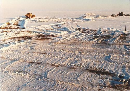
Figure 71. Clearing snow from site
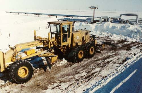
Figure 72. Site after snow removal
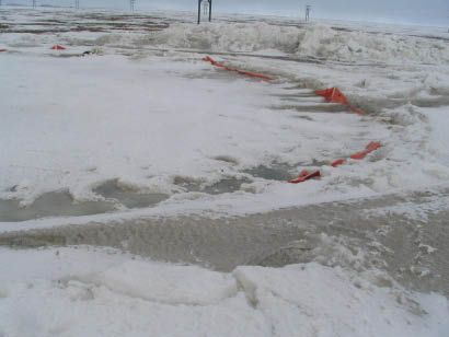
Figure 73. Deep snow cleared from site in spring
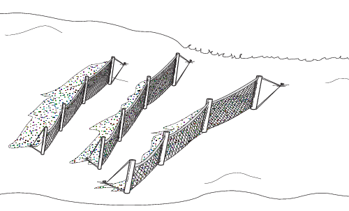
Figure 74. Tiered snow fencing
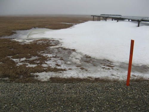
Figure 75. Snow drift on site not protected by snow fencing
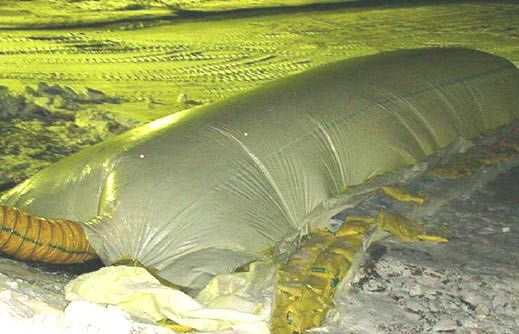
Figure 76. Heated tent to thaw soil
Tactic TR-3: Fertilization for Hydrocarbon Degradation (Bioremediation)
Fertilizer is applied to enhance the ability of soil microbes to metabolize hydrocarbons (i.e., biodegradation). Biodegradation occurs most rapidly when oxygen (O2) is available. Applying nitrate (NO3) fertilizer can enhance biodegradation in the absence of oxygen, because some microbes can use nitrate instead of oxygen. In addition to nitrogen (N), microbes also require phosphorus (P) and potassium (K) for growth and reproduction. Commercially available blended fertilizers supply all three of these essential nutrients. Fertilizer composition varies, and is shown on the bag label as (N-P-K)* followed by the relative percentage of each, e.g., 20-20-10.
Microbes with the ability to degrade hydrocarbons are ubiquitous in the environment, because carbon in organic matter provides the energy that supports many biological processes (Atlas 1985) and because numerous sources of naturally produced hydrocarbons exist (Dragun 1988).
Fertilizer Application
How to Apply
The easiest type of fertilizer to apply is inorganic (mineral) fertilizer, typically packaged in 50–lb. bags of dry pellets. Broadcast fertilizer with a cyclone spreader; these are available in different models that one person on foot can push (Figs. 77–78) or carry (Fig. 79). Larger sites can be treated with a spreader pulled by a 4-wheeler (Fig. 80). Practice and calibration of the spreader are required to distribute fertilizer evenly. A good method is to measure and mark off a small area, fill the spreader with the amount of fertilizer appropriate for that area, and move in a grid pattern at a steady pace over the area multiple times until the spreader is empty.
When and How Often to Apply
Fertilizer can be applied at any time if effects on vegetation are not an immediate concern. See Tactic TR-8 for constraints on fertilization if vegetation is present. If possible, apply fertilizer when soil is at least partially thawed and free of snow and water. The rate and frequency of fertilizer application should be based primarily on hydrocarbon concentrations in soil, as well as changes in hydrocarbon concentrations over time. If concentrations of diesel-range organics (DRO) in soil are < 4,000 mg/kg, a single fertilizer application is probably sufficient. If DRO concentrations are > 4,000 mg/kg, fertilizer should be applied in early summer and fall during two or more successive growing seasons.
What Type to Apply
Ammonium-nitrate fertilizer (e.g., 34-0-0) has the highest concentration of nitrate, making it the most efficient type to apply, but is not always available. Alternatively, a blended fertilizer with a high nitrogen percentage (e.g., 22-4-4) can be used, at a correspondingly higher application rate. A second fertilizer with proportionately more phosphorus and potassium (e.g., 8-32-16) may be applied simultaneously to promote vegetation recovery (TR-8).
How Much to Apply
In agricultural practice, laboratory analysis of nutrient levels in soil is recommended to calculate the type and amount of fertilizer needed. Levels of major nutrients, however, are low enough in most tundra soils that preliminary measurement of nutrient levels is generally unnecessary. Table 2 provides guidelines for rates of fertilizer application, depending on whether fertilization is also being used to promote vegetation recovery. Different fertilizers can be applied simultaneously, but the total amount of fertilizer should not exceed 800 lbs/acre during a single growing season.
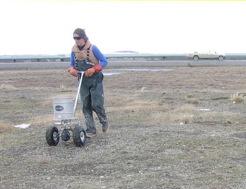
Figure 77. Push spreader
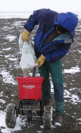
Figure 78. Filling push spreader
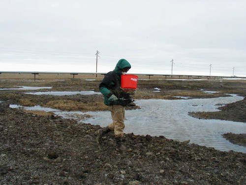
Figure 79. Chest spreader
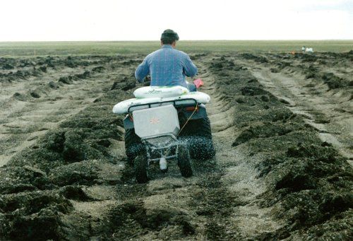
Figure 80. Spreader pulled by 4-wheeler
Table 2. Recommended fertilizer application rates
| Purpose | Fertilizer to Purchase DRO < 4,000 mg/kg | Fertilizer Application Rate (lbs/acre) DRO > 4,000 mg/kg |
|---|---|---|
| Biodegradation | 34-0-0 (use 22-4-4 or similar if 34-0-0 unavailable | 100 to 400, 400 to 800 |
| Biodegradation and plant growth | 22-4-4 and 8-32-16 (use equal amounts of each type) | 100 to 400, 400 to 800 |
Considerations and Limitations
- Fertilizer will have little effect if contaminant levels are toxic to microbes and vegetation, or if the spilled substance created unsuitable pH or salinity conditions.
- Fertilizer is composed of salts and can result in higher electrical conductivity (EC) in soil. Application may not be beneficial at sites where soil EC is elevated (e.g., seawater spills).
- Fertilizer dissolves in water and nitrogen especially can move off-site in surface water; therefore it is not recommended for aquatic tundra.
- Applying fertilizer without a spreader (i.e., scattering by hand) is not recommended, even for small areas, because the spread will be uneven.
- Fertilizer should be stored indoors if possible. Unopened bags can be stored outside for 2-3 weeks in dry weather, but the bags are not air tight and the pellets eventually will absorb water from the atmosphere and stick together in hard clumps, making the fertilizer essentially unusable.
Equipment, Materials, and Personnel
- Necessary quantity of appropriate fertilizer.
- Broadcast spreader (1 operator) – to spread fertilizer.
- Vehicle approved for tundra travel (1 operator) – to pull a broadcast spreader over large sites.
- Personal protection equipment (PPE) (e.g., rubber gloves, dust respirator).
* For historical reasons, the percentage of nitrogen (N) is reported directly, but phosphorus (P) is reported as the fraction of phosphorus oxide (P2O5), and potassium (K) as the fraction of potassium oxide (K2O). This is a standard method used in all fertilizer labeling.
Tactic TR-4: Irrigation
Irrigation is the application of water to improve growing conditions for plants and the soil microbes to metabolize hydrocarbons. Water is applied by flooding (Tactic CR-7), or by spraying with hoses (Fig. 81) and sprinklers (Fig. 82). Water sprayed on a site will have a relatively high concentration of dissolved oxygen, which will enhance the ability of soil microbes to degrade hydrocarbons. Water can be pumped from a lake or pond near the spill site and sprayed onto the surrounding area repeatedly as the water drains back into the waterbody. This method is commonly referred to as the pump-and-treat method.
Flooding for irrigation can be implemented in the same manner described for flooding to remove contaminants (Tactic CR-7). Irrigation by flooding may require land barriers (Tactic CR-5) to maintain desirable water levels and prevent the spread of contaminants into unaffected tundra. Flooding may be appropriate for rehabilitating wet and moist tundra dewatered during cleanup of contaminants.
To protect plants from exposure to extremely cold air, the site may be covered with snow (Fig. 83) or water, which then freezes. The snow and ice will provide moisture during the spring, a time when there is typically little rainfall.
Considerations and Limitations
- This tactic is most applicable during dry periods of the growing season.
- Verify that water is free of hydrocarbons and salts before using it to irrigate tundra.
- Rainfall events may require modification of the watering schedule.
Equipment, Materials, and Personnel
- Water truck (optional) (1 operator).
- Pumps (1 operator).
- Hoses (1 operator) – common sizes are 2- and 3-inch diameter.
- Sprinklers (1 operator).
- Clean water source – may be a nearby pond or creek.
- Power pack - for pumps.
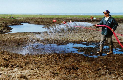
Figure 81. Watering with hoses
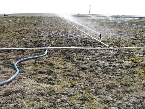
Figure 82. Sprinkler system
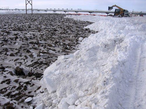
Figure 83. Covering site with snow
Tactic TR-5: Aeration
The primary purpose of aeration is to increase oxygen levels in subsurface soils to enhance degradation of hydrocarbons by soil microbes. Aeration can also improve growing conditions for plants.
Soils may be aerated manually or mechanically, depending on the size and topography of the affected area. Aerate soils manually by repeatedly driving a pitchfork through the tundra root mat and into the organic soil. Aerate soils mechanically by pushing or pulling a rotating barrel fitted with tines over the tundra (Fig. 84). Tines should be long enough to penetrate the root mat and reach the organic soil horizon. Tilling (Tactic TR-6) can also be used to aerate soils. Draining water (Tactic TR-1) from low spots will help aerate soils because the removal of subsurface water will allow air to infiltrate into the subsurface soil (Fig. 85).
Considerations and Limitations
- Mechanical aeration (with a rotating barrel) may not be practicable in tussock tundra or in tundra with flooded troughs.
- Use of vehicles on tundra must comply with applicable tundra travel policies (Tactic P-5).
Equipment, Materials, and Personnel
- Pitchfork (1 worker) – to punch holes through tundra surface.
- Rotating barrel with tines (1 operator) – to punch holes through tundra surface.
- Vehicle approved for summer tundra travel (1 operator) – to pull rotating barrel over tundra surface.
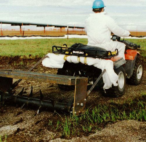
Figure 84. Aerating tundra mechanically
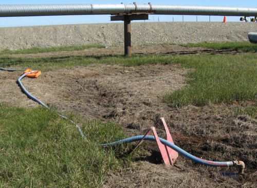
Figure 85. Dewatering to aerate soil
Tactic TR-6: Tilling
Tilling is used primarily to accelerate volatilization of hydrocarbons and to enhance microbial degradation by increasing oxygen availability in soil. Tilling also restores porosity to compacted soils (e.g., after the removal of a gravel pad), and may facilitate plant establishment by creating favorable microsites that are protected from wind and that accumulate surface water. This technique is most appropriate for sites where persistent contaminants (diesel, crude oil) have penetrated deeply into the soil. Visible surface contamination and contaminated vegetation should be removed prior to tilling.
Small areas can be tilled by one person using a rototiller (Fig. 86). Farm equipment such as disc harrows (Fig. 87) or plows may be needed for larger areas. Earth-moving equipment such as front-end loaders, graders, or bulldozers with scarifying or ripper teeth may also be used. Limit tilling to the depth to which contaminants have penetrated. After tilling, re-establish site contours, using surrounding tundra topography as a guide.
Tilling will remove most or all remaining plant cover, and rehabilitation treatments will be needed to restore vegetation. Disruption of the surface increases the likelihood of thermokarst, and backfilling may be necessary to minimize subsidence.
Considerations and Limitations
- This tactic may not be appropriate for sites where the risk of wind or water erosion is appreciable.
- Use of vehicles and heavy equipment on tundra must comply with applicable tundra travel policies (Tactic P-5).
Equipment, Materials, and Personnel
- Rototiller (1 operator) – to rework and aerate soil in small areas.
- Rake (1 worker) – to contour tilled soil in relatively small areas.
- Front-end loader or dozer with ripper teeth (1 operator) – to rework and aerate soil on large sites.
- Grader with scarifying teeth (1 operator) – to rework and aerate soil, and to contour large sites.
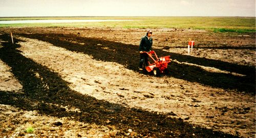
Figure 86. Rototilling contaminated soil
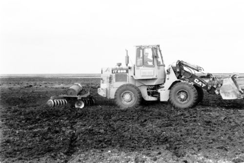
Figure 87. Tilling with disk harrow
Tactic TR-7: Enhancing Natural Revegetation
Natural revegetation occurs when plants re-establish on a disturbed or spill-affected site without seeding or planting. Enhancing natural revegetation, rather than applying plant cultivation treatments, is appropriate under any of the following conditions:
- The effects of the spill and cleanup were minor, so that adequate recovery of surviving vegetation is likely to occur within an accept-able period of time.
- Seeding or planting would interfere with eventual re-establishment of native tundra plants.
Enhancing natural revegetation is generally pre-ferred when the long-term goal is to rehabilitate tundra plant communities with indigenous vegetation. Natural revegetation also increases the probability that the site eventually will resemble the surrounding tundra. Long-term observations have shown that seeding can provide ground cover quickly (1–3 years), however, these grasses are eventually replaced by indigenous species better adapted to the tundra growing conditions. Although restoring the ecological functions and plant communities is possible at a spill site, the goal at most sites is rehabilitation. Rehabilitation is the promotion of native tundra vegetation to reestablish a plant community similar to the one that grew there previously (Figs. 88–91).
The following tactics may be used to enhance natural revegetation:
- Apply fertilizer (Tactic TR-8) to the perimeter of a spill site to increase the seed production and vegetative growth of the surrounding plant community. The wind and wildlife can spread the seeds onto the site.
- Extend the growing season (Tactic TR-2).
- Watering (Tactic TR-4) or dewatering (Tactic TR-1)
Considerations and Limitations
- Analyze soil properties (Tactic AM-5) to evaluate whether natural revegetation is feasible. If the spill residual has created excessively acidic, alkaline, or saline conditions in the soil, plants may not be able to re-establish.
- Concentration of spilled substance in soils cannot be phytotoxic (lethal to plants).
- Monitor the site (Tactic AM-6) for several growing seasons to evaluate revegetation trends.
- Natural revegetation typically requires 15 to 30 years to rehabilitate the plant cover and diversity to pre-disturbance values. The restoration of the original ecosystem functions and values, if possible, will take much longer.
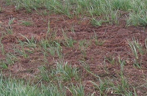
Figure 88. Sedges sprouting in dewatered tundra
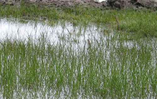
Figure 89. Sedges sprouting in flooded tundra
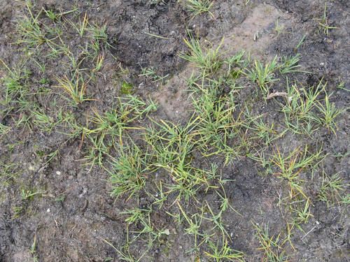
Figure 90. Sedges sprouting in moist tundra
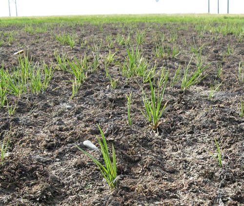
Figure 91. Sedges sprouting in wet tundra
Tactic TR-8: Fertilization for Vegetation Recovery
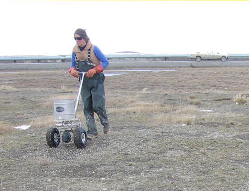
Figure 92. Push spreader
Fertilizer is applied to ensure an abundant supply of the three main nutrients needed by plants for growth and reproduction: nitrogen (N), phosphorus (P), and potassium (K). Commercially available blended fertilizers supply all three of these essential nutrients. Fertilizer composition varies, and is shown on the bag label as (N-P-K)* followed by the relative percentage of each, e.g., 20-20-10. Fertilizer can also be applied to enhance microbial degradation of hydrocarbons (Tactic TR-3).
Fertilizer Application
How to Apply
The easiest type of fertilizer to apply is inorganic (mineral) fertilizer, typically packaged in 50–lb. bags of dry pellets. Broadcast fertilizer with a cyclone spreader; these are available in different models that one person on foot can push (Figs. 92–93) or carry (Fig. 94). Larger sites can be treated with a spreader pulled by a 4-wheeler (Fig. 95). Practice and calibration of the spreader are required to distribute fertilizer evenly. A good method is to measure and mark off a small area, fill the spreader with the amount of fertilizer appropriate for that area, and move in a grid pattern at a steady pace over the area multiple times until the spreader is empty. Fertilizer may also be applied beyond the boundaries of the spill, to enhance seed production in the surrounding tundra and increase seed rain onto the affected area.
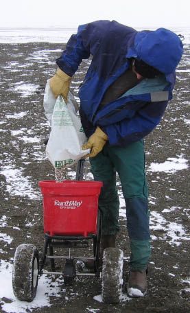
Figure 93. Filling push spreader
When and How Often to Apply
Fertilizer should be applied before 15 July or after 1 September. Elevated nutrient levels are not desirable late in the growing season, as they can delay normal plant senescence and result in winter mortality. One application of fertilizer often is enough to enhance plant growth for several years, but multiple fertilizer applications over one or more growing seasons may be required to meet vegetation performance standards.
What Type to Apply
The type of fertilizer to apply will depend on the treatment goals for the site. Use 20-20-10 if vegetation recovery is the primary goal. Other types and rates of fertilizer may be needed if fertilizer is also being applied to enhance microbial degradation of residual hydrocarbons (Tactic TR-3).
How Much to Apply
Tundra soils are typically deficient in all three major nutrients, so soil testing to determine nutrient requirements is usually not needed. The total amount of fertilizer for most sites should not exceed 200 lbs/acre during a single application and 400 lbs/acre during a single growing season. Rates can be higher for sites where microbial degradation of hydrocarbons is the primary goal (Tactic TR-3).
Table 3 provides ranges for rates of fertilizer application to enhance vegetation recovery. See Tactic TR-3 for fertilizer application rates to enhance microbial degradation of residual hydrocarbons.
Table 3. Recommended fertilizer application rate
| Purpose | Fertilizer to Purchase | Fertilizer Application Rate (lbs/acre) |
|---|---|---|
| Plant Growth | 20-20-10 | 100–200 |
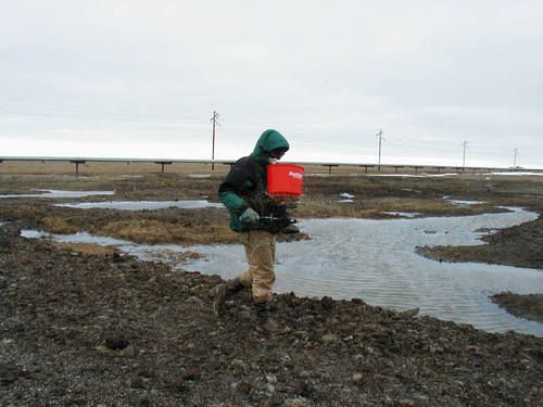
Figure 94. Chest spreader
Considerations and Limitations
- It is easy to apply too much fertilizer, which can cause plant stress, or even kill plants. Weigh fertilizer needed for a given area to prevent the application of too much fertilizer.
- Fertilizer will have little effect if contaminants levels are toxic to microbes and vegetation, or if the spilled substance created unsuitable pH or salinity conditions.
- Fertilizer is composed of salts and can result in higher electrical conductivity (EC) in soil. Application may not be beneficial at sites where soil EC is elevated (e.g., seawater spills).
- Fertilizer dissolves in water and can move off-site in surface water; therefore it is not recommended for aquatic tundra.
- Fertilizer application rates are not the same as nutrient application rates, although both calculations are based on the relative percentages of the nutrients on the bag label. Nutrient application rates are commonly used in agricultural practice, but are not included in this manual.
- Spread fertilizer, seed (Tactic TR-11), and soil amendments (Tactic TR-13) separately. Apply fertilizer or soil amendments, and then apply seed. Do not mix fertilizer with seed or soil amendments for application because the differences in density make proper mixing and spreading with a cyclone spreader difficult.
- Applying fertilizer without a spreader (i.e., scattering by hand) is not recommended, even for small areas, because the spread will be uneven, resulting in patchy growth of plants.
- Fertilizer should be stored indoors if possible. Unopened bags can be stored outside for 2–3 weeks in dry weather, but the bags are not air tight and the pellets eventually will absorb water from the atmosphere and stick together in hard clumps. The fertilizer will become essentially unusable after these clumps form.
- Spreaders that can be pulled by a vehicle may be needed for large sites.
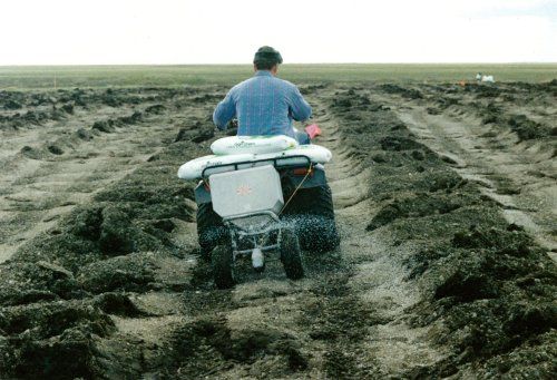
Figure 95. Spreader pulled by 4-wheeler
Equipment, Materials, and Personnel
- Necessary quantity of appropriate fertilizer.
- Broadcast spreader (1 operator) – to spread fertilizer.
- Vehicle approved for tundra travel (1 operator) – to pull a broadcast spreader over large sites.
- Personal protection equipment (PPE) for workers (e.g., rubber gloves, dust respirator).
* For historical reasons, the percentage of nitrogen (N) is reported directly, but P is reported as the fraction of phosphorus oxide (P2O5), and K as the fraction of potassium oxide (K2O). This is a standard method used in all fertilizer labeling.
Tactic TR-9: Transplanting Vegetation
Use transplanting to introduce indigenous plants to a site where vegetation has been severely damaged by a spill. Harvest and transplant appropriate plants adapted to the growing conditions at the site. For aquatic tundra or for areas that are expected to become aquatic due to subsidence, planting sprigs of pendant grass (Arctophila fulva) is appropriate (Figs. 96–98). In moist–wet tundra, transplant sections of tundra sod (tundra plugs) harvested from nearby undisturbed areas (Figs. 99–101). On gravelly areas such as river bars, plant cuttings of willows (Salix spp.) (Fig. 102). On sandy areas such as beaches and dunes, transplant sprigs of dunegrass (Leymus) (Fig. 103). The above-ground portion of the plant may die back after transplanting, but these plants are adapted to disturbance and should regenerate from below-ground rhizomes and buds.
- Harvest pendant grass in aquatic tundra using a shovel with a long blade, such as a drain spade or clam shovel.
- Separate roots from soil and divide clumps into smaller sections or single sprigs for planting (Fig. 104). Keep plants floating in water while this is done, to protect the roots and prevent desiccation.
- Store the plants in large plastic bags or coolers if they will not be transplanted immediately (i.e., within approximately 2 hours).
- To plant sprigs (singly or in small clumps), one worker uses the shovel to pry open a hole, while the other worker inserts a fertilizer tablet and the sprig(s) into the hole (Figs. 97 and 103). The soil all around the sprig(s) should be firmly pressed into place (using the feet) to ensure good contact between roots and soil.
- Harvest tundra plugs using the same type of shovel, or a post-hole digger (Fig. 101), to extract a section of sod approximately 8 inches in diameter and extending well into the rooting zone.
- Keep plugs moist if they will not be transplanted immediately (Fig. 100).
- To transplant plugs, dig holes slightly larger and deeper than the plugs, usually 20–40 inches apart depending on site conditions and rehabilitation objectives (Fig. 99).
- Place 2 fertilizer tablets in each hole, then place each plug with its soil surface slightly below surrounding surface. Replace soil as needed to fill in holes and press plugs into place as for grass sprigs.
- Willow cuttings can be harvested from natural stands before the plants break dormancy in the spring.
- If necessary, cuttings can be stored frozen until the soil is thawed enough for planting.
- Cuttings should be approximately 15–20 inches long and 0.25–0.5 inch in diameter.
- Cuttings can be planted using a long-bladed shovel (as described above for grass sprigs) or a specialized planting tool (dibble), depending on soil conditions.
- Place 1 or 2 fertilizer tablets in each planting hole.
- To reduce moisture loss, plant cuttings with only 2–4 inches above ground.
Considerations and Limitations
- A land use permit from Alaska Department of Natural Resources Division of DNR Division of Mining, Land & Water is required for collecting plants on State of Alaska lands.
- Refer to Streambank Revegetation and Protection (Muhlberg and Moore 1998) for additional details for transplanting vegetation.
- If the site is near the coast or saline substances were spilled, test the soil salt level (Tactic AM-5) to help determine which species, if any, are appropriate to transplant.
- Not all species can tolerate transplanting. For example, a species with a single tap root (an underground structure which cannot be divided without killing the plant) is less likely to survive transplanting than is a species with a fibrous root system (Table 4).
- The advantages of transplanting over seeding are that transplants are usually readily available and transplanting can produce plant cover more quickly than seeding; however, transplanting over large areas is more labor-intensive.
- At some sites, tundra sodding (Tactic TR-10) may be more appropriate than transplanting sprigs or tundra plugs.
Table 4. Examples of plants suitable for transplanting on the North Slope
| Tundra Type | Common Name | Scientific Name | Comments |
|---|---|---|---|
| Aquatic and Wet | Pendant grass | Arctophila fulva | Salt tolerant |
| Wet and Moist | Tall cottongrass | Eriophorum angustifolium | Somewhat salt tolerant |
| Water sedge | Carex aquatilis | ||
| Tundra grass | Dupontia fisheri | Salt tolerant | |
| Moist and Dry | American dunegrass | Leymus mollis | Salt tolerant, adapted to sandy soils |
| Feltleaf willow | Salix alaxensis | ||
| Richardson’s willow | Salix lanata | Generally lower survival than S. alaxensis |
Equipment, Materials, and Personnel
- Large plastic bags, coolers, or 5-gallon buckets – to carry and store collected plants and soil.
- Drain spade or similar (1 operator, 1 planter) – to open holes in the ground to place sprigs or cuttings.
- Drain spade or post-hole digger (1 worker per tool) – to collect tundra plugs.
- Drain spade or similar (1 worker per tool) to dig planting holes for tundra plugs.
- Long knives and/or scissors - for cutting grass clumps into smaller sections.
- 21-gram landscaping fertilizer tablets (1 per sprig, 2 per tundra plug, 1–2 per willow cutting).
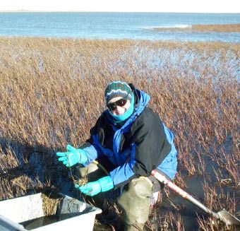
Figure 96. Harvesting pendant grass
Figure 97. Transplanting pendant grass sprigs
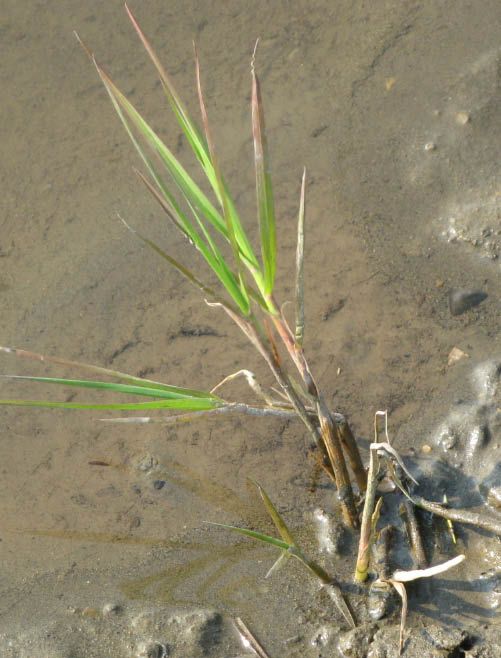
Figure 98. Transplanted pendant grass
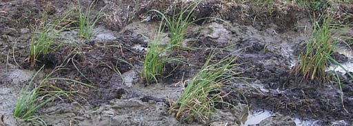
Figure 99. Transplanted tundra plugs
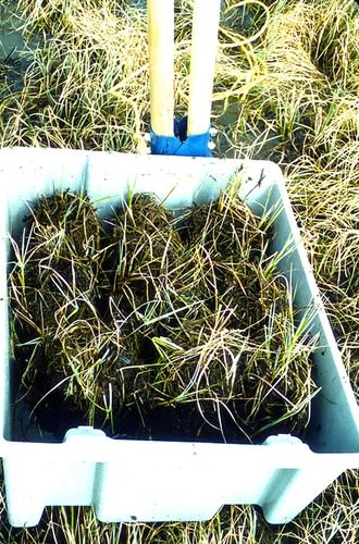
Figure 100. Tundra plugs
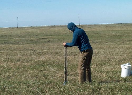
Figure 101. Harvesting tundra plugs
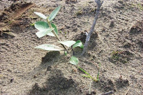
Figure 102. Transplanted willow
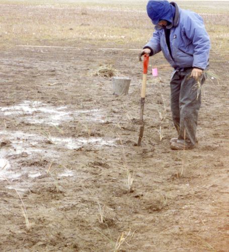
Figure 103. Transplanting dunegrass
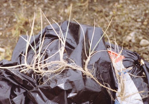
Figure 104. Dunegrass sprigs
Tactic TR-10: Tundra Sodding
Tundra sodding is the transplanting of intact tundra soil and live plant materials to restore native plants in an area where vegetation and soil have been removed to recover contaminants (Fig. 105). In addition, sodding may reduce heat transfer to permafrost, allowing a disturbed site to reach a stable thermal regime more quickly. Some thermokarst should be expected, however, and transplanted sod should contain species adapted to the hydrologic regime expected in the treated area once it has stabilized. This technique is based on traditional ecological knowledge used to build ice cellar roofs in northern Alaska.
Sod can be harvested from a mine site before gravel extraction begins, or from other sites prior to development. If sod must be stored before use, maintaining adequate soil moisture is critical. The best time to harvest sod is when the soil has thawed 6–12 inches. Sod can also be harvested in winter with heavy equipment, but survival will be lower and the cut pieces will be uneven in size and more difficult to transplant.
Sod for small sites can be harvested with hand tools (i.e., knives, shovels, reciprocating saws) (Fig. 106). Mechanical harvesting is recommended for larger sites. A 3.5-ft diameter, 0.75-inch steel disc sharpened and mounted on the bucket of an excavator, similar to an asphalt cutter, has been used successfully to harvest tundra sod in Prudhoe Bay (Fig. 107). The Inupiat term “Nuna ulu” (earth knife) was coined for this rolling cutter. Vertical cuts in the sod are made to a depth of 1–2 ft in PPRendicular directions, and sod is removed with the bucket of an excavator or loader. If a cutting disc is not available, sod can be removed with a loader bucket after making vertical cuts with hand knives (Figs. 108 and 109).
Sod pieces should be as large as practicable during harvesting (Fig. 110), but pieces larger than approximately 4-ft2 are too heavy for one person to carry. If sod must be moved by hand because the site is not accessible to heavy equipment, worker safety can be maximized by using a conveyor belt similar to those used to load airplanes. Non-motorized rails (6–8 ft long) provide a simpler and more mobile alternative (Fig. 111). If the site is road-accessible, an extendable fork lift (“Zoom Boom”) can be used to place pieces that are too heavy to move by hand (Fig. 112). Prior to the placement of sod, fertilizer (20:20:10, granular pellets or tablets) should be placed on the soil surface. The pieces of sod should be placed touching each other to maximize soil contact, making the treated area as similar as possible to undisturbed tundra.
Considerations and Limitations
- A Material Sales Contract with Alaska Department of Natural Resources Division of Mining, Land & Water is needed to harvest sod from a mine site.
- Sodding success depends on transplanting appropriate plant species that are adapted to the growing conditions after the site has stabilized.
- Using thick pieces of sod will minimize heat transfer, but the addition of backfill material before the placement of sod may still be necessary if the transplanted sod is to be at the same grade as the surrounding tundra.
- A permit may be needed from the U.S. Army Corps of Engineers if backfill is used.
- Sodding has been used effectively for moist and wet tundra, and may also work for dry tundra, but is not recommended for aquatic tundra.
- Minimize the time between harvesting and transplanting.
- Surface stability may need to be monitored after transplanting.
- Possible locations for long-term storage of sod are unused areas at a mine site, an uncontaminated reserve pit, or a gravel pad.
- A permit may be needed from the landowner before harvesting tundra sod.
Equipment, Materials, and Personnel
- 12-inch serrated knives (1 worker per tool) – to make vertical cuts.
- Cutting disc (“Nuna ulu”) and excavator or backhoe (1 operator) – to harvest sod.
- Loader (1 operator) – to pick up and load sod at harvest site.
- Flatbed trailer or truck (1 operator) – to haul sod to transplant site.
- Portable aluminum rails or motorized conveyor belts (at least 2 operators) – to move sod beneath pipelines or away from road.
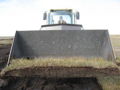
Figure 109. Intact sod harvested with a large loader
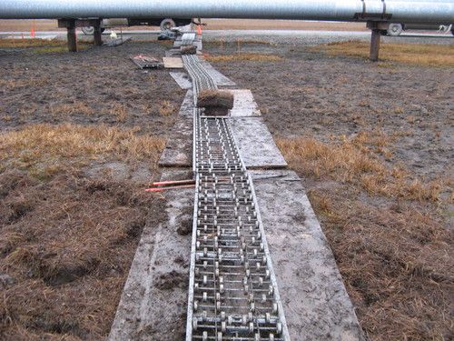
Figure 111. Rails used to move sod onto a site
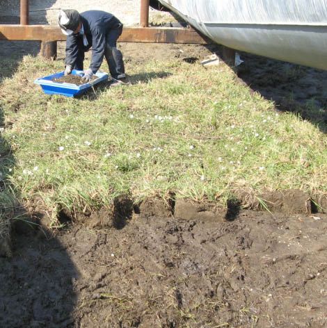
Figure 105. Sodded area
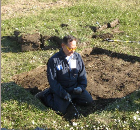
Figure 106. C. Hopson demonstrating sod harvesting
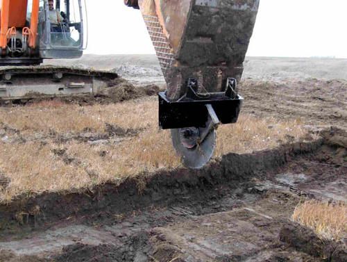
Figure 107. Harvesting sod with a “Nuna ulu”
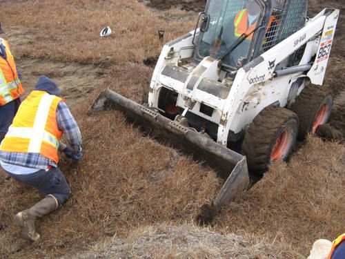
Figure 108. Harvesting sod with a small loader
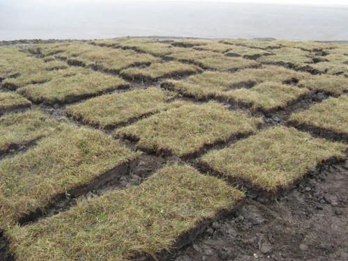
Figure 110. Harvested sod
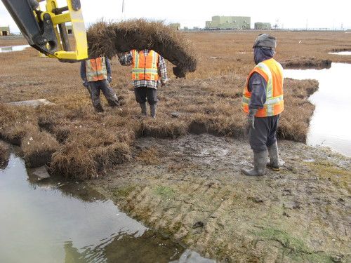
Figure 112. Moving large sod pieces
Tactic TR-11: Seeding
At sites where recovery of the pre-spill tundra vegetation is not feasible, seeding may be necessary in order to establish plant cover. Seeding is used to help control soil erosion, improve the appearance of the site, provide habitat for wildlife, and promote the eventual development of a plant community similar to the original tundra.
The type of seed to use depends on the tundra type, material spilled, and goals of the seeding effort. Cultivars of native grasses are appropriate for many sites, particularly where relatively rapid establishment of plant cover is required. The most commonly used cultivars on the North Slope are ‘Gruening’ alpine bluegrass (Poa alpina), ‘Tundra’ glaucous bluegrass (Poa glauca), ‘Nortran’ tufted hairgrass (Deschampsia caespitosa), and ‘Alyeska’ polargrass (Arctagrostis latifolia). In addition, spiked trisetum (Trisetum spicatum) has been seeded at several sites. It is generally advisable to sow a mixture of at least two species, especially if conditions vary within the site. Seed of native-grass cultivars is available from Alaska commercial growers (e.g., Alaska Garden and Pet Supply in Anchorage). The Revegetation Manual for Alaska, prepared by the Plant Materials Center (Palmer), can provide information about other possible seed sources.
Although the commercially available grasses have been cultivated from species native to northern Alaska, these species are not dominant in undisturbed tundra communities. At sites where the establishment of more typical tundra plants is a priority, sowing seed of indigenous sedges and/or forbs may be appropriate. Indigenous seed can be collected from natural stands, often immediately adjacent to the site. Some species, primarily sedges, can be harvested using a line trimmer with a bag attachment (Grin Reaper™, Environmental Survey Consulting, Austin, TX) (Fig. 113). Other seeds, including legumes, can be collected by hand (Fig. 114). If the seed will not be sown immediately after processing, seal it in plastic bags and store frozen for future use. Little information is available about the long-term viability of seed of tundra plants, so long-term storage is not recommended. Most seeds used for revegetation purposes usually ripen in July and August, but seed collecting is still feasible in September.
Fertilizer should be applied before seeding to provide an adequate supply of nutrients for plant establishment and initial growth (Tactic TR-8). Broadcast large amounts of seed using a cyclone spreader (Fig. 115). The small volume of seeds typically collected by hand must also be spread by hand (Fig. 116). Both methods are best done when there is a light wind (10–15 miles per hour) to help distribute the seeds. A hydroseeder can be used for very large areas. Even distribution of seed will require some practice. One useful method is to measure and mark off an area to be seeded, fill the spreader with the amount of seed appropriate for the given area, and move in a grid pattern at a steady pace over the area multiple times until the spreader is empty.
If the surface is very flat and smooth, it may be helpful to scarify after sowing, to improve seed contact with the soil. A rake can be used to scarify small areas; for larger sites mechanized methods are more practical (e.g., drag a section of chain-link fence behind a four-wheeler).
A list of commercially available grass seed, and seed of indigenous plants that must be collected locally, is provided in Table 5 (next page). This table also recommends species and application rates for different tundra types, including those affected by salts.
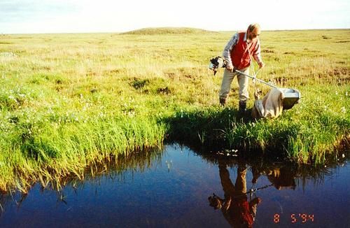
Figure 113. Collecting seed with line-trimmer
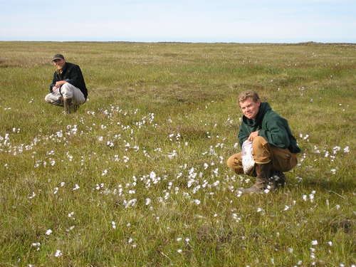
Figure 114. Collecting sedge seed by hand
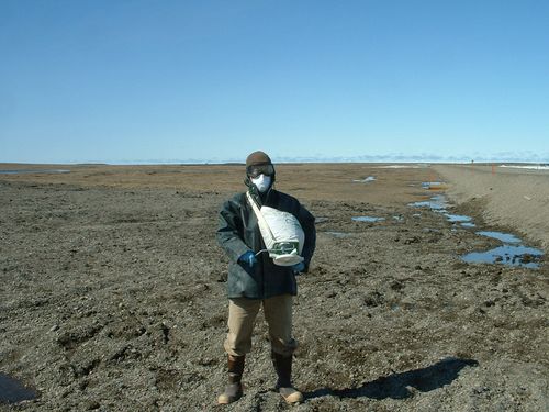
Figure 115. Cyclone spreader
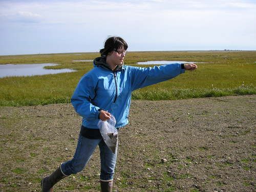
Figure 116. Sowing legume seeds by hand
Considerations and Limitations
- A land use permit from Alaska Department of Natural Resources Division of DNR Division of Mining, Land & Water is required for collecting plants on State of Alaska lands.
- Seeding success depends on soil conditions (nutrient availability, moisture, salinity and contaminant levels). In addition to fertilizer (Tactic TR-8), aeration (Tactic TR-5), irrigation (Tactic TR-4), and tilling (Tactic TR-6) may improve conditions for germination and establishment.
- If the site is near the coast or saline substances were spilled, test the soil for salt before seeding (Tactic AM-5), to help determine what species to use.
- Recently seeded sites may be attractive to wildlife (including birds). If this is not desirable (e.g., due to risks from residual contaminants), it may be necessary to use deterrents and/or hazing to keep wildlife away from the site.
Equipment, Materials, and Personnel
- Necessary quantity of appropriate seed, purchased from a commercial supplier or collected from natural stands.
- Scale - for weighing out seed for each area of site.
- Containers – for weighing seed.
- Cyclone spreaders (1 worker per spreader) – to broadcast seed.
- Vehicle approved for tundra travel (1 operator) – to pull cyclone spreader for larger sites.
- Vehicle approved for tundra travel (1 operator) and chain-link fence – to scarify surface at larger sites.
- Line trimmer with collecting bag (1 operator) – for collecting seed of tundra plants).
- Pruning shears (1 worker) – if needed for collecting seed of tundra plants.
- Rakes (1 worker per rake) – to scarify surface after seeding.
- Paper and cloth bags – for collecting seed of tundra plants.
Table 5. Examples of plant species and seeding rates used for North Slope Tundra Revegetation
| Site Type | Recommended Commercially Available Grass Seed Species | Commercial Species Application Rate (lbs/acre) | Recommended Locally Collected Indigenous Seed Species | Indigenous Species Application Rate (lbs/acre) | Notes |
|---|---|---|---|---|---|
| Wet | Arctagrostis latifolia (Alyeska polargrass), Deschampsia caespitosa (Nortran tufted, hairgrass) | 10–20 | Eriophorum angustifolium (tall cottongrass), Eriophorum scheuchzeri (white cottongrass), Carex aquatilis, Dupontia fisheri | 5 | C. saxatilis and C. membranacea are also suitable, as well as other Carex species adapted to wet conditions |
| Moist | Arctagrostis latifolia (Alyeska polargrass), Deschampsia caespitosa (Nortran tufted hairgrass), Poa glauca (Tundra glaucous bluegrass), P. alpina (Gruening alpine bluegrass) | 20–40 | Eriophorum angustifolium, Carex aquatilis | 5–10 | C. bigelowii may also be used, as well as other Carex species adapted to moist conditions |
| Dry | Poa glauca (Tundra glaucous bluegrass), P. alpina (Gruening alpine bluegrass), Trisetum spicatum (spiked trisetum) | 20–40 | Legumes (e.g., Astragalus alpinus, Oxytropis viscida), Artemisia arctica, Leymus mollis (dunegrass) | 5–10 | -- |
| Salt-affected | Puccinellia borealis (arctic alkaligrass) | 10–20 | Dupontia fisheri, Eriophorum angustifolium, Puccinellia angustata (narrow alkaligrass), Leymus mollis (dunegrass) | 5–10 | D. fisheri for moist-wet sites only |
Tactic TR-12: Backfilling
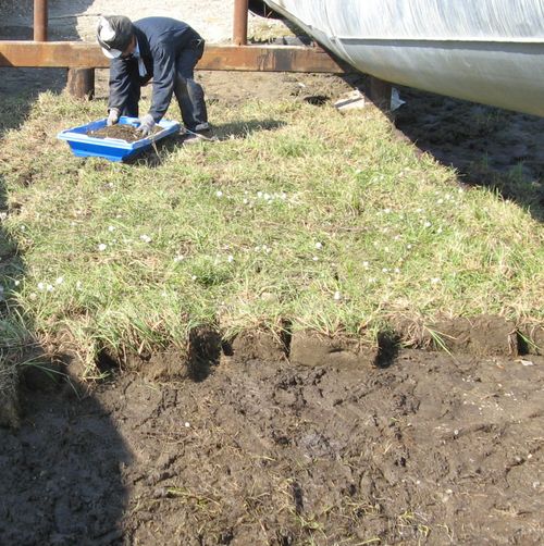
Figure 117. Sodded area
Use backfilling to help stabilize the thermal balance at the tundra surface. The addition of soil can lower the rate of heat transfer into underlying permafrost. If the site remains stable, subsidence of the ground surface caused by thermokarst will be minimized, helping to prevent the impoundment of water and increasing the number of options for revegetation. Backfilling may not be necessary if tundra sod (Tactic TR-10) is added (Fig. 117); sodding is similar to backfilling because relatively thick (6–12 inches) pieces of tundra sod can provide insulation to protect permafrost. Tundra sodding has the added benefit of immediately increasing the plant cover at a site.
Mineral and organic overburden from a mine site often is used as backfill material (Fig. 118). Add enough backfill to allow for settling. Also, the soil may have a high content of ice; add enough backfill material to ensure the volume of soil added will be sufficient after the ice melts. Backfill should be added in lifts. Lifts of backfill should be compacted periodically to minimize settlement.
Considerations and Limitations
- A Material Sales Contract with Alaska Department of Natural Resources Division of Mining, Land & Water, is needed to use overburden from a mine site as backfill.
- Plywood walkways should be set up at the site in order to reduce damage to the adjacent tundra.
- Use of vehicles and heavy equipment on tundra must comply with applicable tundra travel policies (Tactic P-5).
- Surface water should be removed before backfilling.
- Testing may be necessary to determine backfill material properties such as particle size, relative amounts of gravel, sand, and silt.
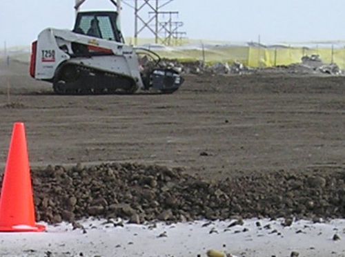
Figure 118. Backfilled area
Equipment, Materials, and Personnel
- Plywood walkways (2 workers) – to prevent trampling of tundra.
- Wheelbarrow (1 worker) – to haul backfill material.
- Shovels.
- Bobcat or front-end loader (1 operator) – to collect and transfer soil used for backfill.
- Dump truck (1 operator) – to transfer backfill material to the site for rehabilitation.
- Wooden lathe - for staking depth of backfill material needed.
Tactic TR-13: Soil Amendments
Soil amendments are used to promote plant growth by improving soil conditions affected by spilled substances. For example, brine spills may create saline conditions, or metabolism of hydrocarbons by soil microbes may acidify soils. If soil testing (Tactics AM-4 and AM-5) or active-layer water monitoring shows that soils are extremely acidic or saline, applying an amendment may be appropriate. Tundra soils can be naturally acidic or saline, amendments should be applied only if levels of acidity or salinity are substantially higher than those in nearby unaffected tundra. Periodic monitoring (bi-weekly) of active-layer water (Tactic AM-4) can track changes in soil properties faster than soil testing. Apply soil amendments during the growing season when soils are free of snow and water, if possible.
Apply lime if soils are too acidic, most plants are not adapted for soils with a pH > 8.
A common technique used to reclaim sodium-affected (sodic) soils is the addition of gypsum or calcium nitrate. These soil amendments displace sodium ions from the soil by replacing them with calcium ions, which adsorb more strongly to soil particles. An adequate water supply is necessary for this chemical exchange to occur, and adequate drainage is necessary to flush the sodium from the affected soil. Chloride ions do not bind strongly to soil, and will be flushed out with the sodium ions. Adding gypsum will not necessarily be effective in all saline soils. Laboratory testing is required to determine if gypsum will improve soil conditions (Table 6).
Table 6. Examples of soil amendments used for North Slope tundra
| Amendment | Purpose |
|---|---|
| Lime (calcium carbonate CaCO3) | To buffer overly acidic soil caused by a spill of an acidic substance, or by microbial degradation of hydrocarbons |
| Gypsum (calcium sulfate and water, Ca•SO4 and H2O) | Calcium source to remove salt (sodium and chloride ions) after a seawater or other type of salt spill |
| Liquid calcium nitrate | Calcium source to remove salt (sodium and chloride ions) after a seawater or other type of salt spill |
How Much to Apply
Application rates of soil amendments are site-specific and should be calculated by a soils laboratory. Provide the laboratory with a target pH range (background concentration), and the laboratory will calculate the application rate of a given soil amendment based on results from soil testing. The manufacturer of liquid calcium nitrate will provide information on how much is needed (based on laboratory data) for a certain area to achieve a certain salinity range.
How to Apply
Lime and gypsum are available in powder or granular form, typically packaged in 50–lb. bags. Broadcast lime or gypsum with a cyclone spreader, which are available in different capacities and models that one person on foot can push (Figs. 119–120) or carry (Fig. 121). Larger sites can be treated with a spreader pulled by a 4-wheeler (Fig. 122). Practice and calibration of the spreader are required to distribute lime or gypsum evenly. A good method is to measure and mark off a small area, fill the spreader with the amount of lime or gypsum appropriate for that area, and move in a grid pattern at a steady pace over the area multiple times until the spreader is empty.
Lime or gypsum may be applied simultaneously with fertilizer (Tactics TR-3 and TR-8).
Liquid calcium nitrate can be applied to small sites using weed sprayers or watering cans, or to larger sites using a hydroseeder or similar piece of equipment. The distribution method is similar to that for powder or granular amendments. A given amount of product is sprayed methodically over a given area to achieve even distribution at the correct application rate. Calibrate the sprayer before use.
Considerations and Limitations
- To determine the types and amounts of amendments needed, soil samples typically are sent to a soils laboratory that routinely conducts analyses for agricultural purposes, such as the University of Alaska Fairbanks Agricultural and Forestry Experiment Station in Palmer, AK. Some analytical laboratories, where soils are analyzed for contaminants, may also be equipped to calculate the need for soil amendments.
- Extremely alkaline tundra soils are not readily correctable with amendments.
Equipment, Materials, and Personnel
- Necessary quantity of appropriate soil amendment.
- Cyclone spreader (1 operator) – to broadcast powdered soil amendments.
- Vehicle approved for tundra travel (1 operator) – to pull a cyclone spreader over larger sites (optional).
- Weed sprayer or watering can (1 operator) – to spray liquid soil amendments on small sites.
- Hydroseeder or similar equipment (2 operators) – to spray liquid soil amendments on larger sites.
- Personal protection equipment (PPE) - to keep workers safe (e.g., rubber gloves, dust respirator).
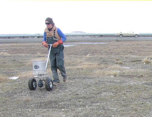
Figure 119. Push spreader
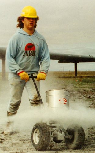
Figure 120. Applying lime
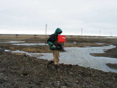
Figure 121. Chest spreader
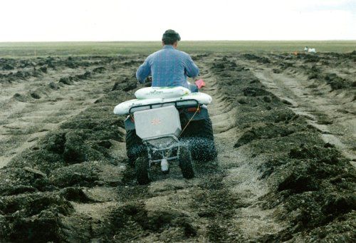
Figure 122. Spreader pulled by 4-wheeler
Tactic AM-1: Delineation and Sampling of the Spill Area
It is important to mark the spill area so that its boundaries can be located at a later date, especially if the site is snow covered. Airborne Forward-Looking Infrared (FLIR) photography can be used to identify the spill area even if the site is snow covered (Fig. 123). Delineation should begin as soon as possible after the spill has been contained. Correct the boundary location as needed. The contrast between clean and contaminated snow is especially useful for visually delineating affected areas. Even relatively clear fluids such as diesel, methanol, and produced water, can cause dramatic changes in the color and physical characteristics of snow.
To delineate large spill areas (>1,000 square feet), two workers walk the perimeter of the spill in opposite directions from a common starting point, and place markers every 50 to 100 feet to provide a visible boundary. The two workers should meet midway around the perimeter of the spill area, and then retrace each other’s routes to confirm the delineation. While walking, they look for visible impacts, including spilled substance on the ground; discoloration of plants or soil; sheen on standing water or foliage; and dead or damaged vegetation. For smaller spills, a single worker may perform the delineation. Aerial photographs are of great value for identifying and mapping site features and spill boundaries.
A scaled map of the site probably will be required for planning, monitoring, and reporting purposes and will be most useful if prepared using professional surveying methods (Figs. 124–125). As soon as practical after containment, a sampling system should be implemented, to be used for monitoring (Tactics AM-2 and AM-4). The preferred method is systematic sampling at nodes on a grid system, which facilitates the unbiased selection of sampling locations (Fig. 126). Depending on the shape of the affected area, the grid should be a square or rectangle that is large enough to encompass the containment area and some adjacent unaffected (reference) tundra. Vegetation monitoring plots should be located at the same locations where samples were collected.
For affected tundra areas that are ~0.5 acre (~150′ x 150′) in size, a grid with 15-ft spacing would create 100 nodes where lines intersect. Typically, samples are collected at a subset of nodes, chosen using an unbiased selection method. This approach can be used for a site of any size simply by expanding the grid. For larger sites (> 1 acre), the distance between nodes can be changed to create a reasonable number of potential sampling locations, or to meet specific sampling objectives. For example, the spill area may be subdivided into areas with high, medium, and low concentrations of contaminants (Fig. 127). If the sampling plan stipulates that 10 samples should be collected from each area, the size of the grid can be adjusted to provide at least 10 potential sampling locations in each area. When the affected tundra includes patterned ground, the grid distances should be less than the average polygon diameter to avoid sampling bias among topographical features (e.g., polygon centers, rims, and troughs).
Two methods exist for establishing the grid system at a site. Importantly, neither method interferes with cleanup operations, because permanent stakes or markers are not needed to locate sampling stations within the spill area. Nevertheless, sample stations can be relocated with good precision. The first method uses permanent markers (e.g., survey nails, wooden stakes, or rebar) that are driven into the ground in two parallel rows on opposite sides of the spill, and that are separated by the appropriate distance between grid nodes. Each marker is labeled with a row number (e.g., 1 through 10), letter (e.g., A, B, C), or distance from a corner of the grid (e.g., 0, 2, 4, 6 for a 2-ft grid). Individual sampling points are then located by stretching a tape between the corresponding end stakes and sampling is done at specified distances along the tape. The second method uses a “virtual grid” created with computer software (e.g., AutoCAD). The coordinates of selected sample stations are then uploaded to a field computer, which is used to navigate to the sample location (Fig. 128). The use of a virtual grid generally requires contracting the services of a professional surveyor, although other personnel with special training and equipment can also establish a virtual grid.
A variety of maps probably will be needed and should include at least the following elements:
- Location of the spill source.
- Boundary of the affected area.
- Areas of low and high concentration of spilled substance.
- Adjacent roads and structures.
- Tundra types within affected area.
- Sensitive areas and habitats (identification may require special training or additional work).
- Nearby drainages or water bodies, most likely direction of water movement, location of culverts in road.
- Slope and topography (e.g., elevation contours).
- Location of monument used to control survey locations and elevations.
- Sampling grid that can be overlaid on the site map.
- Sampling locations (including background samples), preferably at nodes on sampling grid.
- Vegetation study plots, transects, or photo-plot locations (include direction of photo).
- North arrow, scale and approximate latitude and longitude of the site.
Considerations and Limitations
- Technical literature (e.g., U.S. Environmental Protection Agency) is available to help design a plan for sampling and data collection.
- The area of an uncontained spill will expand with time on all types of tundra.
- The boundaries of spills of saline or water-soluble substances are difficult to delineate visually, especially when snow is absent. These spills tend to spread rapidly except in winter, when the fluids mix with snow and freeze. If salts or other water-soluble compounds are present in high enough concentrations, the vegetation may die or show signs of stress (wilting, discoloration, loss of foliage) in affected areas.
- Seasonal frost action in the soil may push wooden stakes out of the ground over time (i.e., frost-jacking). Wooden stakes may also be disturbed by winter vehicle traffic in the area. Metal rebar may pose a physical hazard. Survey pins (e.g., 9-inch nails) with bristles are preferred because they do not pose a safety hazard, they are less affected by frost-jacking, and they can be relocated with a metal detector.
- Plywood boardwalks may be needed to protect tundra from trampling.
- Considerations for site assessments used by the Alaska Department of Environmental Conservation are found in 18 AAC 78.090.
- This tactic has been adapted from Tactics T-1 and T-2 in the Alaska Clean Seas Technical Manual.
Equipment, Materials, and Personnel
- Permanent markers (9-inch nails or wooden lath stakes) (1 or 2 workers) – to mark spill perimeter and grid system.
- Handheld GPS unit (1 operator) – to provide coordinates for initial site delineation.
- Professional survey equipment and personnel (variable) – to permanently mark grid layout, sampling locations, and to provide a scaled drawing.
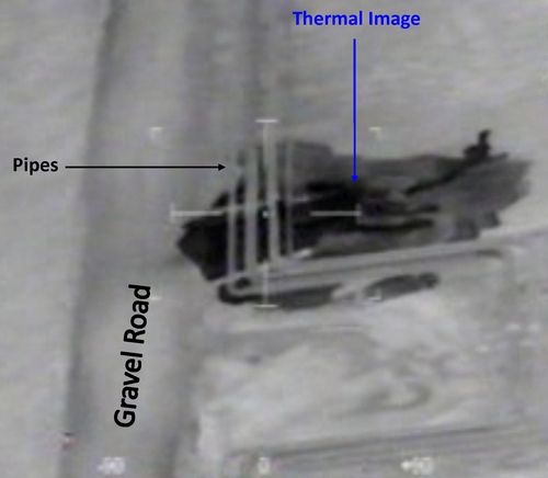
Figure 123. FLIR image of spill area
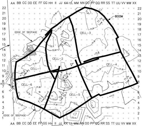
Figure 124. Sampling grid and elevation contours
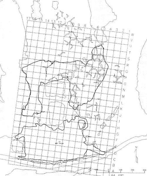
Figure 125. Sampling grid
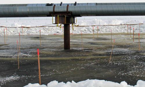
Figure 126. Wooden lathe showing sampling locations on grid
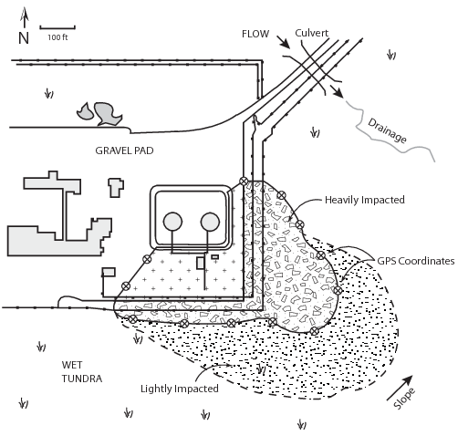
Figure 127. Typical site layout
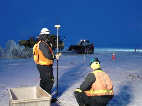
Figure 128. Marking sampling locations
Tactic AM-2: Field Indicators
Field indicators are standardized, simple measurements or qualitative observations that can be made periodically at a site to monitor and document contamination, treatment effectiveness, and ecological damage associated with the cleanup operation. Field indicators also provide a context for interpreting chemical analyses of soil samples (Tactic AM-4 and Tactic AM-5) and data on vegetation response (Tactic AM-6). Field indicators are important components of a baseline site assessment or monitoring program.
Four categories of field indicators may be measured or observed:
- Spill Residue: Treatment progress may be monitored by visually assessing the degree of contamination on soil and vegetation (Table 7).
- Soil Conditions: The rooting zone, where contamination is most harmful to plants, usually extends 1 to 8 inches (2 to 20 centimeters) below the ground surface. Evaluating the infiltration of contaminants into this zone provides a helpful indicator of how vegetation is likely to respond (Table 8).
- Ecological or Physical Damage: Cleanup operations can result in physical damage with long-term ecological consequences, including thawing of permafrost (thermokarst). Monitoring physical damage can help determine the point at which intensive treatment should stop. The thickness of the active layer (thaw depth) should be measured periodically, so that thermokarst can be monitored over time (Table 9).
- Ecological recovery: Recovery at a site is indicated by growth of native plants and re-establishment of drainages, and a stable thermal regime typical of permafrost terrain.
Table 7. Field sample coding sheet for visual assessments of oilspills on tundra*
| Parameter | Measurement or Observation |
|---|---|
| Residue thickness on ground or vegetation |
|
| Residue consistency |
|
| Residue expulsion (residual hydrocarbons can be squeezed out of surface organics or soil with foot pressure) |
|
| Residue color |
|
* Field indicators for other types of residues must be developed on a case-by-case basis. Adapted from Cater and Jorgenson 1999
Table 8. Some field indicators of soil conditions*
| Parameter | Measurement or Observation |
|---|---|
| Organic layer |
|
| Mineral soil layer |
|
| Mineral soil texturea |
|
| Thaw depth |
|
| Water depth |
|
| Containment infiltration |
|
* Adapted from Cater and Jorgenson 1999
a Classification based on Natural Resources Conservation Service, U.S. Department of Agriculture (Schoeneberger et al. 2002)
Table 9. Some field indicators for physical or ecological damage *
| Parameter | Measurement or Observation |
|---|---|
| Tundra type |
|
| Vegetation cover (Tactic AM-6) | Cover estimates (0 to 5%, 6 to 25%, 26 to 50%, 51 to 75%, 76 to 95%, 96 to 100%) for shrubs, graminoids (i.e., grasses and grass-like plants), mosses, and bare soil |
| Vegetation damage (Tactic AM-3) |
|
| Birds and mammals (use data form) |
|
* Adapted from Cater and Jorgenson 1999
Measure and observe field indicators at pre-established sampling points, preferably at discreet points on a sampling grid. The number and locations of sampling points should be established by agreement between the responsible party and regulatory agencies. Field sampling points should represent the entire site, with no bias to either heavily or lightly impacted areas. The number of sampling points that are needed will depend on the degree of contamination and the size of the affected area. A small site with heavy contamination may require a relatively intensive sampling approach (e.g., 10 field sampling points per 0.1 acres). For larger sites, spread field sampling points out more widely to characterize the entire site (e.g., 1 sample per 0.2 acres). In many cases, it will be appropriate to divide the site into zones of severity (e.g. lightly, moderately and heavily affected); several samples should be collected in each zone. Field indicators should also be measured in similar tundra types in the surrounding area unaffected by the spill (background or reference areas) for comparison.
Field sampling points preferably should be established at nodes on the surveyed sampling grid (Tactic AM-1). Ideally, the same measurements and observations should be made at all field sampling points.
If necessary, use survey nails or other permanent markers to physically mark the sampling points and record their locations on a scaled site map (Tactic AM-1) so they can be accurately relocated in the future. If an individual sampling location is not located at a node on the grid, record a waypoint, or the distance and direction of the sample location from a grid node. Most observations of field indicators are specifically related to the tundra surface. When subsurface soil observations are necessary, dig a small test pit and examine the sidewall of the pit, or cutting out a soil sample for easier observation.
Sample datasheets for recording field indicator data are located at the end of this section.
Considerations and Limitations
- Avoid placing stakes in locations that may interfere with treatment operations.
- Water-soluble spill residues may not be visible on the tundra surface.
- Most observations or measurements of field indicators require a thawed active layer and the absence of snow cover.
- Use plywood walkways to minimize trampling of site.
Equipment, Materials, and Personnel
NOTE: Generally a team of two workers measures and records observations of field indicators.
- Ruler or measuring tape – to measure residue on tundra surface and the depth of infiltration.
- Metal probe – to measure depth of thaw, water depth.
- Shovel – to dig small test pit to observe soil horizons.
- Large survey nails, wooden laths, or steel “rebar” stakes – to mark areas where field indicators were measured or observed so they can be relocated during subsequent monitoring events.
- GPS – to record sample point locations.
- Standard data forms - to record observations.


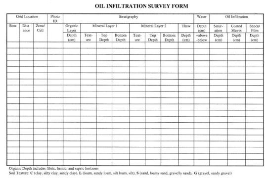
Tactic AM-3: Preventing Damage from Clean-up Activities
The goal of this tactic is to help responders stop clean-up activities before too much tundra damage occurs. There is no precise definition of too much damage, however, due to site-specific differences that determine the treatment goals and selection of tactics. Thus, making the key decision during a clean-up response when the risk of physical damage from continued clean-up activity does, or does not, outweigh the benefits of recovering additional spill residuals will depend on many factors.
When field indicators (Tactic AM-2) are used to monitor clean-up effectiveness and tundra damage, responders have access to the most recent information for using the decision trees to guide the clean-up (Tactic P-1). Guidelines are presented here to help determine when clean-up activities should stop. The guidelines rely on simple observations, but some training of observers may be necessary to provide accurate information. For example, damage to soil is often readily visible but disturbance to vegetation often is more difficult to determine, especially in winter. The short growing season in the Arctic often means that a meaningful assessment of vegetation recovery may not be possible until 3–5 years after a spill.
The three most likely forms of damage to result from a spill clean-up are the compression of the organic mat, the tearing of belowground plant materials (e.g., roots and rhizomes), and the removal of vegetation and soil. Damage is less likely to occur when soils are frozen, but accurately assessing tundra damage often is not possible until summer. Soil compression is dependent on the depth to which the soil is frozen, the soil type, the amount of water in the soil, as well as the weight of equipment, the number of passes of people or equipment over a specific area. Soils that are wet, or that were frozen when wet, have pore spaces filled with water (or ice), and are less susceptible to compression and shearing forces than drier soils that have air voids. In general, wet and moist tundra will be less susceptible than dry tundra to compression and shearing forces.
In winter, the first indication that tundra disturbance is possible is the incorporation of dead plant leaves (e.g., plant litter) into the snow pack, which indicates the snow pack is no longer thick enough to provide a protective layer to the tundra surface.
According to the Alaska Department of Natural Resources (DNR), vegetation damage is defined as any visible mechanical alteration of plant anatomy such as broken or abraded branches of shrubs and scuffed or crushed tussocks, while soil damage is defined as any visible depression or displacement of soil resulting in a defined track. Tables 10 and 11 provide additional information that can be used as an overall guideline to assess six levels (from negligible to severe) of physical damage to the spill site (see also Tactic AM-2).
When assessing the level of damage, it is important to compare the spill site with adjacent undisturbed tundra of the same type. For example, undisturbed dry tundra may naturally have areas of exposed soil. This ranking system is intended to be rapid, thus the estimates of cover are subjective and different from the quantitative method used in Tactic AM-6. To rapidly assess the level of damage, an observer visually estimates the proportion of an area (e.g., a treatment cell) according to the damage variables. This rapid assessment method is most useful for describing large differences.
Considerations and Limitations
- If soil samples are collected to assess the depth of penetration by contaminants, the water content and bulk density of the soil also should be estimated to determine the likelihood of soil compression.
Equipment, Materials, and Personnel
- Grid system - for sampling (Tactic AM-1).
- Sample containers, drying oven, and scale - for calculating water content and bulk density.
Table 10. Classification and description of damage levels for tundra
| Damage Level | Description |
|---|---|
| Negligible 0 | No impact to slight scuffing of higher microsites. Disturbance not evident from the air or on air photos. |
| Low 1 | The decrease in vegetation cover is <25% and the amount of exposed soil is <5%. Compression of standing plant litter and slight scuffing of soil is evident in wet, moist or dry tundra; tussocks or hummocks scuffed. |
| Moderate 2 | The decrease in vegetation cover is 25–50%, and/or exposed soil is 5–15%. Compression of mosses and standing plant litter is evident in wet and moist tundra; tussocks or hummocks are crushed; portions of spill site may appear wetter than surrounding area; some tearing of vegetative mat within moist tundra along rivers and in dry tundra. |
| High 3 | The decrease in vegetation cover is >50–75%, and/or exposed soil is >15–25%. Standing water is apparent on spill site that probably was not present before the spill; moist tundra changing to wet tundra; crushed tussocks or hummocks nearly continuous; change in vegetative composition; in moist tundra along rivers and in dry tundra, vegetation mat and ground cover substantially disrupted. |
| Very high 4 | The decrease in vegetation cover is >75–95% and/or exposed soil is >25–90%. Ground depressions common in moist tundra. In wet tundra, thermokarst and ponding may result in a substantial area that is covered by water, especially where extensive areas of vegetation and surface soils have been churned or displaced. Dry tundra appears as barrens with only occasional patches of vegetation remaining. |
| Severe 5 | Vegetation removal is essentially complete (>95%) and exposed soil is nearly continuous (>90%). Some colonizing plants may be present, but vegetation cover is less than 5%. |
Table 11. Variables used to rank the damage level for tundra
| Damage Variable | Damage level 0 | Damage level 1 | Damage level 2 | Damage level 3 | Damage level 4 | Damage level 5 |
|---|---|---|---|---|---|---|
| Vegetation Reduction (% cover) | 0–4 | 5–24 or increase | 25–50 | 51–75 | 76–95 | >95 |
| Vegetation Height (% of reference) | 90–110 | 75–89 or >110 | 50–74 | 25–49 | 5–24 | <5 |
| Exposed Soil (% cover) | 0 | 1–5 | >5–15 | >15–25 | >25–90 | >90 |
| Microrelief (cm) (Depression, Compaction, Thermokarst, Excavation) | 0 | 1–4 | 5–14 | 15–24 | 25–100 | >100 |
Tactic AM-4: Testing Soil and Water for Contaminants
Government agencies may require periodic laboratory analysis of soil and water during treatment and rehabilitation of a spill site (Fig. 129). This tactic describes procedures for sampling and analysis to measure contaminants in tundra soil, surface water, and in supra-permafrost water (i.e., subsurface water within the active layer of thawed soil). Sampling and analysis plans must be approved by the Alaska Department of Environmental Conservation (ADEC). Select laboratory analyses by referring to regulations used by ADEC (18 AAC 75.341, 345 and 18 AAC 70.020) to establish chemical-specific screening criteria and cleanup levels for soil and groundwater. Workers must comply with Occupational Safety and Health Administration regulations, which require special training for sampling hazardous substances.
Selection of Sample Sites
To allow testing for a correlation between analytical results and field indicators, collect analytical samples at the same locations where field indicators are monitored (Tactic AM-2) whenever possible. If samples for analytical analysis are collected at new locations, field indicator data should also be collected at these locations. Avoid collecting analytical samples from a location that has been disturbed by monitoring for field indicators.
The number of locations selected for sampling, and the frequency of sampling must be approved by agencies. An intensive treatment and monitoring program may require ongoing sampling (weekly to monthly), while a less intense program may require annual monitoring. Sampling is normally performed when the soil is thawed.
Preventing Cross-Contamination
Avoid cross-contamination of samples by using proper sample-handling techniques and decontamination practices. Work in pairs with one person labeling jars and writing field notes without handling contaminated material, while the other person collects samples and handles sampling equipment. Decontaminate sampling equipment before each sampling event to ensure collection of representative samples and to prevent cross-contamination. Use a laboratory-grade detergent and preferably hot potable water to clean sample equipment. Rinse with tap water followed by multiple rinses with de-ionized water.
Soil Sampling Procedures
A typical cross-section of tundra soil has two distinct layers differentiated by color and texture (Tactic P-2). The upper horizon consists of dark organic soils, usually with dense plant roots and is often smooth in texture. The lower, mineral horizon is usually sandy or silty in texture, and the color is often lighter, or gleyed (grey and/or blue).
Collect samples separately for the upper (organic) soil horizon and the lower (mineral) horizon. Stainless steel spoons, disposable sample scoops, shovels, and hand augers may be used to collect surface/near-surface samples.
Surface soil samples must be collected from freshly uncovered soil to minimize the loss of any volatile compounds, and transferred directly from the freshly uncovered soil to the laboratory-supplied sample container. If a sample is to be collected in a test pit that has been open for longer than one hour, a minimum of 3 inches of surface soil should be removed immediately before collection.
Surface Water Sampling Procedures
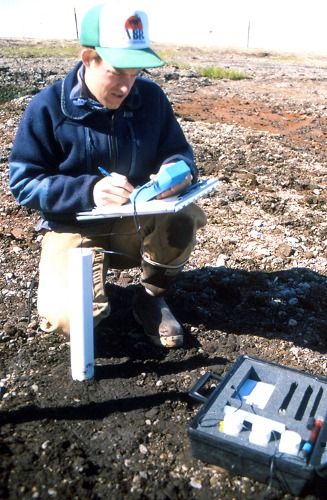
Figure 129. Monitoring water in the active layer
Collect samples of surface water by gently immersing a clean sample bottle in the body of water. Avoid disturbing sediments in the immediate vicinity of the collection point before sample collection.
Field measurements of water quality parameters may be recorded after sample collection, including:
- Temperature
- pH
- Specific conductance (SC), which is calculated from electrical conductivity (EC)
- Dissolved oxygen
- Oxidation reduction (Redox) potential
Calibrate the instruments in the field before use.
Testing Surface Water for Salt Content during Flooding or Flushing
When treating a spill of a saline substance by flooding or flushing, use a hand-held field probe to monitor the EC of the water before and after it is applied to the tundra, to provide immediate confirmation that salts are being removed. EC values should decrease with successive flooding treatments as salts become diluted. However, when salts have penetrated into the soil, EC may increase temporarily when these salts are flushed out of the soil. If the soil is frozen, this increase may not occur until the soil thaws sufficiently to allow the salts to become mobile. Calibrate the conductivity meter before collecting data. Many conductivity probes automatically convert EC values to SC (EC standardized to 25oC) to allow comparison of measurements made at different temperatures. If necessary, manually convert EC readings to SC values. A variety of units are used for recording conductivity in water; the standard international unit is the Siemen (S). Conductivity meters usually display results in microSiemens/cm (µS/cm), or in milliSiemens (mS/cm). Another unit, the “mhos” is often used in the United States. Fortunately, 1 mhos = 1 S, and 1 µmhos/cm = 1µS/cm (see Tactic AM-5).
Procedures for Sampling Water from the Active Layer of Soil
Collecting samples of water below the tundra surface (i.e., in the active layer of thawed soil or supra-permafrost groundwater) requires the installation of monitoring wells (Fig. 129). Before each sampling event, a minimum of three to five well volumes of water should be purged from the well. This will remove any stagnant water in the well casing and ensure that the sample originates from the soil surrounding the well. Use a disposable bailer or a peristaltic pump to purge wells. Collect purged water in drums and dispose of it according to applicable regulatory guidelines.
Use a sterile, disposable bailer to collect water samples from wells. Immediately place water into sample containers and preserve as specified by the analytical laboratory.
Laboratory Analysis Plan
The type of substance spilled and the sample media dictate the analyses to be used. Laboratories will provide sample containers and specify required sample quantities. Table 12 provides examples of sampling and analysis parameters.
| Spilled Substances | Analysis | Matrix | EPA/ADEC Method | Containers (will vary with lab ) | Preservation, Holding Time |
|---|---|---|---|---|---|
| Crude Oil, Diesel, Gasoline | Gasoline Range Organics (GRO) | Water | AK 101 | 40-ml VOA, TLS lid | HCI to pH<2, Cool to 4oC, extract and analyze in 14 days |
| Crude Oil, Diesel, Gasoline | Gasoline Range Organics (GRO) | Soil | AK 101 | 4-oz Amber glass, teflon-lined septa (TLS) lid | Methanol, <25oC, extract and analyze in 28 days |
| Crude Oil, Diesel, Gasoline | Diesel Range Organics (DRO) | Water | AK 102 | 2-1L Glass Amber | pH<2 (HCI), 4o+2oC, 7 days to extract, analyze <40 days |
| Crude Oil, Diesel, Gasoline | Diesel Range Organics (DRO) | Soil | AK 102 | 4-oz Amber glass, TLS lid | 4o+2oC, 14 days to extract, analyze <40 days |
| Crude Oil, Diesel, Gasoline | Residual Range Organics (RRO) | Water | No water method | -- | – |
| Crude Oil, Diesel, Gasoline | Residual Range Organics (RRO) | Soil | AK 103 | 4-oz Amber glass, TLS lid | 4o+2oC, 14 days to extract, analyze <40 days |
| Crude Oil, Diesel, Gasoline | Total Polynuclear Aromatic Hydrocarbons (PAH) | Water | 610, 625, 8021 B, 8260 C | 40 ml VOA, TLS lid | pH<2 (HCI), 4o+2oC/14 days |
| Crude Oil, Diesel, Gasoline | Total Polynuclear Aromatic Hydrocarbons (PAH) | Soil | 8270, 8100, or 8310 | 4-oz Amber glass, TLS lid | 4o+2oC/14 days or per method requirements |
| Crude Oil, Diesel, Gasoline | Benzene, Toluene, Ethylbenzene, and Xylenes (BTEX) | Water | 8260M (SIM)/602, 624 | 40-ml VOA, TLS lid | HCI pH<2, cool to 4oC, extract and analyze in 14 days |
| Crude Oil, Diesel, Gasoline | Benzene, Toluene, Ethylbenzene, and Xylenes (BTEX) | Soil | 8260M/8021 B/6240/AK 101 | 4-oz Amber glass, TLS lid | 4o+2oC, extract and anlyze in 14 days or per method requirements |
| Glycol | Water | 8015 M, 8015 B | 40-ml VOA | 4o+2oC/7 days or per method requirements | |
| Glycol | Soil | 8015 M, 8015 B | 4-oz jar | 4o+2oC/7 days or per method requirements | |
| Therminol | Water | 8015 M, 8015 B | 40-ml VOA | 4o+2oC/7 days or per method requirements | |
| Therminol | Soil | 8015 M, 8015 B | 4-oz jar | 4o+2oC/7 days or per method requirements | |
| Methanol | Water | 8015 M, 8015 B | 40-ml VOA | 4o+2oC/7 days or per method requirements | |
| Methanol | Soil | 8015 M, 8015 B | 4-oz jar | 4o+2oC/7 days or per method requirements | |
| Salinity | Water | SM-22520B | 250-ml plastic | 4o+2oC/14 days or per method requirements | |
| Salinity | Soil | SM-22520B | 4-oz jar | 4o+2oC/14 days or per method requirements |
Table 12. Examples of sampling and analysis parameters
Tactic AM-5: Testing Soil and Water for Revegetation
This tactic describes procedures for conducting tests on soil and water to provide information to help select tundra rehabilitation tactics. Some of the procedures and protocols are similar to those used to test soil for contaminants. Sample soils and water in affected and unaffected (i.e, reference) tundra to:
- Determine if salinity is suitable for germination and establishment of plants.
- Determine whether pH conditions are suitable for plant growth and microbial activity, and
- Determine baseline conditions that can be used to compare with conditions in the future
- Determine if tundra affected by a spill is substantially different from undisturbed tundra
Collect at least 3 to 6 soil samples from a site to account for variability. For larger sites, it may be useful to collect 3 to 6 samples from the area with the highest concentration of contaminants, and 3 to 6 samples from areas with moderate or lower contaminant concentrations. In addition, collecting 3 to 6 soil samples from a nearby unaffected area with similar vegetation and soil will allow the affected tundra are to be compared with undisturbed tundra, which may be important for selecting tundra rehabilitation tactics. For example, tundra near the coast can have naturally saline soils, indicating that salt-tolerant species may be needed to revegetate a site. Tundra soils typically have a surface organic layer overlying a mineral soil layer with very different characteristics, and these differences must be accounted for when using soil characteristics to make decisions.
Collect soil samples from a pit dug using a clean shovel. If necessary, collect samples at different depths to represent the entire active layer (surface to frozen subsurface). Segregate the organic rooting mat, which typically has a high content of plant roots and partially decomposed organic matter, from lower layers of mineral soil. Place each sample in resealable plastic bags (e.g., Ziploc® brand), or in DuPont™Tyvek® bags typically used by geologists. Label each bag with the site name, date, unique sample identification, and the initials of the person collecting the sample. Request that the soils laboratory analyze the organic soil layer separately from the mineral soil layer. Refrigerate soil samples 4 ± 2°C (36–43°F) until analysis to minimize biological activity. Soil samples should be air dried or frozen if it is not possible to keep them refrigerated before delivery to the laboratory within 14 days of being collected. If samples are air dried, ensure they are not exposed to hot temperatures.
Testing for Salinity
The salinity of soil and water is important to tundra plants because high concentrations of salts, such as sodium chloride, can interfere with the absorption of water into the plants, even when a substantial amount of water is present in the soil. Salts may also interfere with the ability of plants to absorb mineral nutrients (e.g., nitrogen and phosphorus). Electrical conductivity (EC) is used as a measure of the concentration of water-soluble salts in soil and water; high EC values indicate high salinity.
Tundra soil is considered saline if EC is greater than 4 dS/m (deciSiemens per meter) which is equivalent to 4 mmhos/cm (millimhos per cm). EC can also be measured in water bodies that may have been affected by a spill. EC in natural tundra water bodies is typically <800 µS/cm (microSiemens/centimeter) which is equivalent to 800 µmhos/cm (micromhos/centimeter). In tundra that is naturally saline (e.g., salt marshes), EC can be much higher. See Table 13 for conversion factors for the most common EC units.
Table 13. Conversion factors for electrical conductivity units
| From | To | Multiply by: |
|---|---|---|
| dS/m | µS/cm | 1000 |
| dS/m | mmhos/cm | 1 |
| mmhos/cm | µS/cm | 1000 |
The standard method used by a laboratory to express salinity is to measure EC of a saturated extract at 25°C. A soil extract is prepared by mixing a known mass of soil with a known volume of deionized water, usually at a 1:1 ratio. The laboratory procedure used to measure electrical conductivity in soil is described in Soil Survey Investigations Report No. 42, Soil Survey Laboratory Methods Manual, Version 4.0, November 2004, USDA, NRCS. A similar method using a portable EC meter can be used in the field to rapidly assess soil salinity. A portable EC meter also can be used in the field to rapidly assess salinity of surface water. Because salinity is affected by temperature, field measurements of EC should be converted to specific conductance, which standardizes EC values to 25°C. EC results from a laboratory are reported at 25°C and do not need to be converted.
Field observations can also provide good evidence of salinity. Note the presence of free salt on the soil surface, the presence of bare ground when the surrounding tundra is vegetated, and the presence of salt-tolerant plant species. Using portable EC meters in the field to measure EC in soil and water is often helpful to aid in planning the location and number of samples to be collected for laboratory analysis.
Testing specifically for concentrations of sodium and chloride may be needed. Ion specific probes that are supported by portable field meters are available. Sodic soils have high concentrations of sodium and are a specific type of saline affected soil. If salinity is high and the pH is high (>8.5), the sodium adsorption ratio (SAR) should also be calculated. SAR takes into consideration that the adverse effect of sodium is moderated by the presence of calcium and magnesium ions.
Seeding or transplanting salt-tolerant plants may be appropriate for salt-affected sites if no salt-tolerant plants are growing nearby to revegetate the area (Tactic TR-9). Soil amendments (Tactic TR-13) may be appropriate if the site is too saline for any plant growth (Tables 14 and 15). Flooding (Tactic CR-7) or flushing (Tactic CR-8) also may be appropriate.
Table 14. Electrical conductivity values in tundra surface water and vegetation tolerance
Range of electrical conductivity in Natural Tundra Water Bodies
| dS/m and mmhos/cm | mS/cm | Description | Vegetation Tolerance |
|---|---|---|---|
| < 0.8 | < 800 | Freshwater | All plants |
| 0.8 – 2.0 | 800 – 2000 | Brackish | Most plants (some growth limitation) |
| 2.0 – 6.0 | 2000 – 6000 | Saline | Some plants (growth limitation) |
| > 6.0 | > 6000 | Very saline | Salt-tolerant plants only |
Table 15. Electrical conductivity ranges in soil for plants
Electrical Conductivity Ranges in Soil for Plants (multiple units presented)
| Non salt-tolerant | Salt-tolerant | Normal Range in Tundra Soil |
|---|---|---|
| 0.3 – 4.0 mmhos/cm | 4.0 – 6.0 mmhos/cm | <2 mmhos/cm |
| 300 – 4000 mmhos/cm | 4000 – 6000 mmhos/cm | < 2000 mmhos/cm |
| 0.3 – 4.0 dS/m | 4.0 – 6.0 dS/m | <2 dS/m |
Testing for pH
Use portable meters to measure pH in soil and water rapidly, and to help in the planning of the location and number of samples to be collected for laboratory analysis. Compare results to back-ground levels near the site and to the normal range for tundra on the North Slope. If the pH in soil is above or below normal range (5.2 to 7.8) for tundra, a soil amendment may be appropriate. A pH range of 6.0 to 7.0 is optimal for availability of nutrients in soil. However, other pH values may be normal for that area. If sample results are similar to background levels, soil amendments are not necessary (Table 16).
Table 16. Normal pH in tundra
Normal pH Range in North Slope Tundra
| Matter | pH range |
|---|---|
| Soils | 5.2 – 7.8 |
| Water bodies | 6.5 – 8.5 |
Testing for Physical and Chemical Characteristics of Soil
Testing for physical and chemical characteristics of soil can provide important information for selecting tundra rehabilitation tactics. The relative amounts of gravel, sand, silt, and clay, and the amount of organic matter are physical characteristics important to plant growth. Laboratories first separate each sample into the coarse earth (particles > 2 mm in size) and fine earth fractions (particles < 2 mm in size). Gravel typically comprises the coarse earth fraction in tundra soils. The fine earth fraction includes sand, silt, and clay. Most laboratory tests are conducted using only the fine earth fraction. The amount of organic matter in soil is important because it enhances water and nutrient holding capacity and improves soil structure. Some laboratory tests may not be possible if the sample is mostly organic matter. If the soil is analyzed for soil nutrients, the pH of the sample also should be analyzed because plants growing in soil with extremely high or low pH may not be able to absorb soil nutrients. Compare results from the affected area with undisturbed tundra to determine the relative importance of soil characteristics for vegetation recovery in the affected area (Table 17).
Considerations and Limitations
- Soil sampling is typically done when the active layer is thawed.
- If more than one plant community or soil type is found on a site, additional sampling will be required.
- Comparison of results between different soil horizons and tundra types on a site is not valid. Also, samples must be compared with background results from similar soils and plant communities, to determine the extent to which the area was affected by a spill.
- Mechanical analysis for soil samples may be necessary for backfill material imported to a site.
Equipment and Personnel
- Shovel (1 worker) – to collect soil samples.
- Ziploc® or other plastic bags (1-gallon size) or DuPont™Tyvek® bags – to store samples.
- Labels and notebook – for recording sample identifications bags and soil horizons.
- Cooler and blue ice – to store and ship samples to the soils laboratory.
Table 17. Laboratory tests for physical and chemical soil properties
Physical
| Soil Property | Normal Range in Tundra Soila |
|---|---|
| Gravel | 15b |
| Sand | 18–69 |
| Silt | 15–64 |
| Clay | 10–39 |
| Organic Matter (%) | 5.7–55.5 |
Chemical
| Soil Property | Normal Range in Tundra Soila |
|---|---|
| pH | 5.2–7.8 |
| Salinity | |
| Electrical Conductivity (dS/m) | <2 |
| Sodium Adsorption Ratio | <13c |
| Available Nutrients (mg/kg) | |
| Nitrogen, Ammonium | 8.7–19.5 |
| Nitrogen, Nitrate | 5.5–15.2 |
| Phosphorus | 0.1–15 |
| Exchangeable Cations (mg/kg) | |
| Potassium | 92–349 |
| Calcium | 1399–7381 |
| Magnesium | 93–627 |
| Sodium | 15–150b |
- a Reference values (except where noted) from Walker (1985).
- b Reference values from unpublished ABR data.
- c Reference value from Brady and Weil (1996).
Tactic AM-6: Monitoring Vegetation
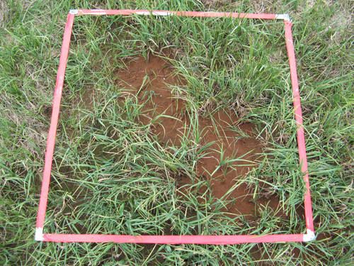
Figure 130. 1-m2 vegetation quadrat
The health, cover, and composition of tundra vegetation are measured before and after treatment, to aid in assessing impacts and monitoring recovery of tundra affected by a spill. The effects of a spill can also be assessed by comparing vegetation in a spill area with vegetation in an area unaffected by the spill. The fastest field techniques for monitoring vegetation use visual observations of plant health, repeat photography (photo-trend plots), or the semiquantitative method of estimating plant cover in plots of a specified size (area method). The preferred method for monitoring vegetation is the point-intercept method, however, because it provides more objective data. The potential for revegetation of a site can be assessed with test plots to determine whether seeds will germinate or plants can establish and survive under certain conditions. Identification of plant species and implementing some of the monitoring techniques may require special expertise. If appropriate, consult with a plant scientist or other qualified person to develop a monitoring plan or to conduct the vegetation monitoring.
Plant Health
The health and condition of tundra plants growing on the site is evaluated qualitatively based on visual examination. Look for signs of growth, reproduction (flowers, seeds, spreading by roots) and vigor (health) using undisturbed vegetation not affected by the spill near the site as a reference. Signs of poor growing conditions, stress, or toxic effects of contaminants may include dead plants or dead leaves, discoloration such as yellow leaves, stunted plants, lack of reproduction, and slow or no growth. Remain alert to evidence of grazing by animals (e.g., torn leaves, scat, foot prints), which may have removed a significant amount of plant parts. Evaluation of the condition of plants does not require special expertise, although some training by experts in plant science may be useful to identify less obvious effects that may be important for achieving the treatment goals.
Photo-Trend Plots
Using photographs to monitor permanent plots is a popular and effective technique for monitoring the revegetation of affected tundra over successive growing seasons. This technique is most useful if the same view direction is used each time, and is dependent upon being able to relocate the plot. The corners of permanent plots can be marked with metal nails (6 to 9 inches in length) that are commonly used by surveyors, or with wooden or steel “rebar” stakes. A common method used to delineate individual plots in a photograph is to place a 1–meter-square quadrat frame made of white PVC pipe or aluminum flat-bar on the tundra (Fig. 130). A stake is then driven into the tundra soil in opposite corners to mark the location of the quadrat permanently. Prepare a map of the plot locations (Tactic AM-1) so that plots can be easily relocated over multiple years for repeat sampling. If possible, stand in the same location, and use the same camera focal length and exposure settings each time a plot is photographed. It can be very helpful to use a photo of the plot taken previously as a reference when re-taking photographs. Some photo-trend plots of experimental oil spill sites on the North Slope have been documented for over 25 years, providing valuable information about the recovery of the tundra.
Vegetation Cover
Vegetation cover is the vertical projection of vegetation from the ground as viewed from above. Vegetation cover is commonly estimated using either point or area methods (Bonham, 1989; NARSC, 1999).
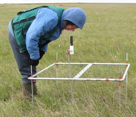
Figure 131. Laser and point-frame
- Point intercept methods are based on the number of “hits” on vegetation out of the total number of points measured; either the point “hits” a part of the plant (e.g., leaf or stem) or it does not (Fig. 131). The point is defined by shining the beam of a hand-held laser vertically down through the vegetation (i.e., PPRendicular to the ground). The plant is hit when the light beam is visible as a red dot on a plant part. A second method is based on an observer looking past cross hairs made of thin wire (similar to a gun sight); the plant is hit when it lies beneath the cross hairs. The cross hairs are mounted in a tube or frame (i.e., a point frame) (Fig. 131). The laser and sighting tube are mounted on a steel rod that is driven into the ground to provide a stable sampling point. Similarly, the stability of a point frame is maintained by driving the four legs in each corner of the frame into the tundra. Many points must be sampled in groups along a line or within a frame to provide useful information. The percent cover of live plants is calculated as the total number of hits on live plants divided by the total number of points sampled. For example, if 50 points are measured and 10 points have “hits” on plants, then the total cover of live plants would be 20%. Tundra vegetation often has multiple layers, or canopies, which can result in a plant cover >100% when using point intercept methods.
- Area methods involve placing a quadrat (a square or circle) of known area on the ground surface, and visually estimating plant cover classes (Fig. 130). Typical examples of classes are 1–5%, 6–25%, 26–50%, 51–75%, and >75%. A 20- by 50-centimeter frame is a popular quadrat size for estimating tundra vegetation cover. Usually a number of quadrats (10–30) are evaluated at a site to reduce the bias inherent in this method. If more than one person is estimating plant cover, the observers should train together and compare estimates within the same quadrats to minimize the amount of error. Although more simple to implement than the point-intercept method, the area method is greatly affected by the biases of each observer. Thus, estimates of vegetation cover using the area method are more difficult to defend as being objective and repeatable.
Vegetation Composition
Tundra vegetation communities typically include a variety of vascular plants, including sedges, grasses, forbs (broad-leaved herbs), and dwarf or prostrate shrubs, as well as nonvascular plants such as mosses, liverworts, and lichens. The number of plant species is a useful gauge of vegetation recovery at a site when compared to similar, unaffected tundra areas. Accurate identification of plants requires some training or special expertise in plant science. An on-line information source for identification of Alaskan tundra plants is available in the PLANTS DATABASE (http://www.plants.usda.gov/) maintained by the U.S Department of Agriculture. Technical publications and flower guides commonly used to identify tundra plants are provided in Table 18.
Table 18. Sources used to identify tundra plants
| Vascular Plants (Sedges, Grasses, Forbs, Shrubs) | Source |
|---|---|
| Flora of Alaska and Neighboring Territories | Hultén 1968 |
| Willows of Interior Alaska | Collet 2004 |
| Field Guide to Alaskan Wildflowers | Pratt 1989 |
| Wetland Sedges of Alaska | Tande and Lipkin 2003 |
| Flowering Plants of the High-Arctic | Threlkeld 1991 |
| Wildflowers of the Yukon and Northwestern Canada, including adjacent Alaska | Trelawny 1983 |
| Alaska Trees and Shrubs | Viereck and Little 2007 |
| The Alaska Vegetation Classification System | Viereck et al. 1992 |
| Nonvascular Plants (Mosses and Lichens) | Source |
|---|---|
| American Arctic Lichens | Thomson 1984, 1997 |
| Wetland Indicator Bryophytes of Interior and South Central Alaska | Seppelt et al. 2006 |
| Mosses, Lichens and Ferns of Northwest North America | Vitt et al. 1988 |
Revegetation Test Plots
Before undertaking large-scale treatments such as excavation for offsite disposal (Tactic CR-13), fertilizing (Tactic TR-3 and TR-8), seeding (Tactic TR-11), or transplanting (Tactic TR-9), it may be desirable to determine if current conditions are toxic to plants. Establish plots to test seed germination or transplant survival. Seed germination and other test plots can be marked and monitored using the same methods described above.
Bibliography
Agosti, J., and T. Agosti. 1973. The oxidation of certain Prudhoe Bay hydrocarbons by microorganims indigenous to a natural oil seep at Umiat, Alaska. Pages 80-85 in Proceeding of the Symposium on the Impact of Oil Resource Development on Northern Plant Communities. Institute of Arctic Biology, Univ. of Alaska, Fairbanks, AK.
Alaska Clean Seas. 2009. Alaska Clean Seas Technical Manual, Volume 1: Tactics Descriptions. Developed for Alyeska Pipeline Service Company, EXXON Company, BP Exploration, and ARCO Alaska, Inc.
Alexander, M. 1995. How toxic are toxic chemicals in the soil? Environmental Science and Technology 29:2713-2717.
Atlas, R. M. 1985. Effects of hydrocarbons on microorganisms and petroleum biodegradation in arctic ecosystems. Pages 63-99 in F. R. Engelhardt, ed., Petroleum effects in the arctic environment. Elsevier Applied Science Publishers , New York.
Atlas, R. M., and J. Brown. 1978. Introduction to the workshop on ecological effects of hydrocarbon spills in Alaska. Arctic 31:155-157.
Atlas, R. M., A. Sexstone, P. Gustin, O. Miller, P. Linkins, and K. Everett. 1978. Biodegradation of crude oil by tundra soil microorganisms. Pages 21-28 in Biodeterioration, Proceedings of the 4th International Symposium. Berlin, Germany.
Auerbach, N. A., M. D. Walker, and D. A. Walker. 1997. Effects of roadside disturbance on substrate and vegetation properties in arctic tundra. Ecological Applications 7:218-235.
Barker, M. 1985. Two-year study of the effects of a winter brine spill on tussock tundra. Final rep. prepared for ARCO Alaska, Inc., Anchorage, AK. 92 pp.
Barnes, D. L. , and D. M. Filler. 2003. Spill evaluation of petroleum products in freezing ground. Polar Record 211:385-390.
Bech, C., and P. Sveum. 1991. Spreading of oil in snow—a field experiment. Proceedings of 14th annual arctic and marine oil spill program. Vancouver, BC. Environ. Canada, Ottawa, CA.
Behr-Andres, C., J.K. Wiegers, S. Forester, and and J.S. Conn. 2001. Tundra Spill Cleanup and Remediation Tactics: A Study of Historic Spills and Literature. State of Alaska Department of Environmental Conservation, Juneau, AK.
Bergstein, P. E., and J. R. Vestal. 1978. Crude oil biodegradation in arctic tundra ponds. Arctic 31:158-169.
Billings, W. D. 1973. Arctic and Alpine Vegetation: Similarities, Differences, and Susceptibility to Disturbance. BioScience 23:697-704.
———. 1974. Arctic and alpine vegetation: plant adaptations to cold summer climates. Pages 403-443 in J. D. and R. G. Barry Ives, (eds.). Arctic and Alpine Environments. William Clowes and Sons Ltd., Great Britian.
Bishop, S. C., J. G. Kidd, T. C. Cater, L. J. Rossow, and M. T. Jorgenson. 1998. Land rehabilitation studies in the Kuparuk Oilfield, Alaska, 1997. Twelfth annual report prepared for ARCO Alaska, Inc., Anchorage, AK, by ABR Inc. —Environmental Research and Services. 66 pp.
———. 1999. Land rehabilitation studies in the Kuparuk Oilfield, Alaska, 1998. Thirteenth annual report prepared for ARCO Alaska, Inc., Anchorage, AK, by ABR Inc.—Environmental Research and Services. 72 pp.
Blackburn, A. J., H. M Clilverd, R. Samuel, K. M. Holland, and D. M. White. 2007. Chemistry of North Slope, Alaska, Lakes and Reservoirs: September 2005 to May 2007. University of Alaska Fairbanks, Water and Environmental Research Center, Fairbanks, AK. Report No. INE/WERC 07.13.
Bliss, L. C. , G. M. Courtin, D. L. Pattie, R. R. Riewe, D. W. Whitfield, and P. Widden. 1973. Arctic tundra ecosystems. Annual Review of Ecological Systematics 4:359-399.
Bonham, Charles D. 1989. Measurements for Terrestrial Vegetation. John Wiley & sons,New York.
BP Exploration (Alaska), Inc. 1994. 1993 X-pad restoration progress report cooperative reclamation plan. September 1, 1993 to August 31, 1996. Environmental Regulatory Affairs, Anchorage, Alaska.
Braddock, J. F., and and K. A. McCarthy. 1996. Hydrologic and microbiological factors affecting persistence and migration of petroleum hydrocarbons spilled in a continuous-permafrost region. Environmental Science and Technology 3:2626-2633.
Brady, N. C., and R. R. Weil. 1996. The Nature and Properties of Soils. Prentice-Hall, Upper Saddle River, NJ.
Brendel, J. E. 1985. Revegetation of arctic tundra after an oil spill: a case history. Pages 315-318 in Proceedings of 1985 Oil Spill Conference: American Petroleum Institute, Environmental Protection Agency, United States Coast Guard.
Brendel, J. E., and T. G. Eschenbach. 1985. Check valve 23 revegetation study. Pages 230-239 in M. L. Lewis, ed. Proc. Eighth Ann. Meet. Int. Soc. Petr. Indust. Biol. Northern hydrocarbon development environmental problem solving. Banff, Alberta.
Brown, A. L., and J.D. McKendrick. 1987. Joint industry/agency/university revegetation feasibility project. Fifth Symposium on Coastal and Ocean Managemnet (Coastal Zone ‘87). Seattle, WA.
Brown, J., B. E. Brockett, and K. E. Howe. 1984. Interaction of gravel fills, surface drainage, and culverts with permafrost terrain. Alaska Department of Transportation and Public Facilities, Fairbanks, AK. Rep. No. AK-RD-84-11. 35 pp.
Brown, J., R. Haugen, and S. Parrish. 1975. Selected climate and soil thermal characteristics of the Prudhoe Bay Region. J. Brown, editor. Ecological Investigations of the Tundra Biome in the Prudhoe Bay Region, Alaska. University of Alaska, Fairbanks, Alaska. 215 pp.
Brown, J., W. Rickard, and D. Victor. 1969. The effect of disturbance on permafrost terrain. Cold Regions Research and Engineering Lab, Hanover, NH. CRREL Special Report 138.
Brown, R. W., R. S. Johnston, and K. Van Cleve. 1978. Rehabilitation problems in alpine and arctic regions.Pages 23-44 in Reclamation of Drastically Disturbed Lands. ASA-CSSA,
Buchkina, N. 1998. Effects of native cover plants on mechanical stability of tundra soils. Journal of Soil and Water Conservation July.
Burgess, R. M., T. C. Cater, and M. T. Jorgenson. 1996. In situ bioremediation at the drill site 1 and 2 relief pits, Prudhoe Bay, Alaska, 1991-1995. Final report prepared for CH2M Hill, Anchorage, AK, by ABR Inc.—Environmental Research and Services, Fairbanks, AK. 30 pp.
———. 1996. In-situ Bioremediation at the DS-L2 Spill, Prudhoe Bay, Alaska, 1992-1995. Final Report prepared for ARCO Alaska, Inc. and CH2M Hill, by ABR Inc.—Environmental Research and Services, Fairbanks, AK. 24 pp.
Burgess, R. M., T. C. Cater, M. T. Jorgenson, and B. A. Anderson. 1995. Ecological Impact Assessment and Restoration Options for the Pt. McIntyre Oil Spill. Final Report prepared for CH2M Hill, by ABR Inc.—Environmental Research and Services, Fairbanks, AK. 63 pp.
Burgess, R. M., M. T. Jorgenson, T. C. Cater, B. A. Anderson, L. L. Jacobs, and B. E. Lawhead. 1995. Ecological impact assessment and restoration options for the DS-5 oil spill. Final Report prepared for CH2MHill and ARCO Alaska, Inc., Anchorage, AK, by ABR Inc.—Environmental Research and Services, Fairbanks, AK. 63 pp.
Burgess, R. M., E. R. Pullman, T. C. Cater, and M. T. Jorgenson. 1999. Rehabilitation of salt-affected land after close-out of reserve pits. Third Annual Report prepared for ARCO Alaska, Inc., Anchorage, AK, by ABR Inc.—Environmental Research and Services, Fairbanks, AK. 48 pp.
Campbell, W. B., R. W. Harris, and R. E. Benoit. 1973. Response of Alaskan tundra microflora to a crude oil spill. Pages 53-62 in Proceedings of the Symposium on the Impact of Oil Resource Development on Northern Plant Communities. Institute of Arctic Biology, Univ. of Alaska, Fairbanks, AK.
Cargill, S. M., and and F.S. Chapin III. 1986. Establishment of native plants on disturbed soils in arctic Alaska. P.J. Webber, ed. Restoration and Vegetation Succession in Circumpolar Lands. Proceedings of the 7th Conference Comite Arctique Int. Reykjavik, Iceland.
———. 1987. Application of successional theory to tundra restoration: A review. Arctic and Alpine Research 19:366-372.
Cater, T. C. , R. M. Burgess, and M. T. Jorgenson. 1996. In-situ bioremediation of contaminated tundra at the central gas facility, Prudhoe Bay, Alaska, 1995. Final Report prepared for ARCO Alaska, Inc., and CH2M Hill, Anchorage, by ABR Inc.—Environmental Research and Services, Fairbanks, AK. 21 pp.
———. 1997. Assessment of phytotoxicity of tundra soil contaminated with diesel fuel, Drill Site-L2, Prudhoe Bay, Alaska, 1996. Final Report prepared for ARCO Alaska, Inc., Anchorage, AK, and CH2M Hill, Inc., Anchorage, AK, by ABR Inc.—Environmental Research and Services, Fairbanks, AK. 28 pp.
Cater, T. C. and M. T. Jorgenson. 1993. Land Rehabilitation Studies in the Kuparuk Oil Field, Alaska, 1992. Seventh Annual Report prepared for ARCO Alaska Inc. and Kuparuk River Unit, by ABR Inc.—Environmental Research and Services, Fairbanks, AK. 38 pp.
———. 1994. Remediation of gravel and tundra at the SWPT Pad, Kuparuk Oil Field, Alaska, 1993. Unpublished Report prepared for ARCO Alaska, Inc. , by ABR Inc.—Environmental Research and Services, Fairbanks, AK. 46 + appendices pp.
———. 1995. Long-term ecological monitoring of tundra affected by a crude oil spill near Drill Site 2U, Kuparuk Oilfield, Alaska. 1994 Annual Report prepared for ARCO Alaska, Inc., Anchorage, AK, and Kuparuk River Unit, Anchorage, AK, by ABR Inc.—Environmental Research and Services, Fairbanks, AK. 42 pp.
———. 1996. Land Rehabilitation Studies in the Kuparuk Oil Field, Alaska, 1995. 10th Annual Report prepared for ARCO Alaska, Inc. and the Kuparuk River Unit, by ABR Inc.—Environmental Research and Services, Fairbanks, AK. 72 pp.
———. 1996. Sewage sludge application on a thick gravel pad in the Kuparuk Oilfield, Alaska, 1989-1995. Final Report prepared for ARCO Alaska, Inc., Anchorage AK and Kuparuk River Unit, Anchorage, AK, by ABR Inc.—Environmental Research and Services, Fairbanks, AK. 34 pp.
———. 1999. Assessing damage from hydrocarbons and cleanup operations after crude oil spills in Arctic Alaska. Final Report prepared for ARCO Alaska, Inc., Anchorage, AK and Kuparuk River Unit, Anchorage, AK, by ABR Inc.—Environmental Research and Services, Fairbanks, AK. 80 pp.
Cater, T. C. , E. R. Pullman, R. M. Burgess, and M. T. Jorgenson. 1998. Cleanup and bioremediation of crude oil and methonal at Drill Site 16, Prudhoe Bay oilfield, Alaska, 1997. Final Report prepared for ARCO Alaska, Inc., Anchorage, AK, by ABR Inc.—Environmental Research and Services, Fairbanks, AK. 48 pp.
Cater, T. C. , L. J. Rossow, and M. T. Jorgenson. 1999. Long-term ecological monitoring of tundra affected by a crude oil spill near Drill Site 2U, Kuparuk Oilfield, 1996. Annual Report prepared for ARCO Alaska, Anchorage, AK, by ABR Inc.—Environmental Research and Services, Fairbanks, AK. 53 pp.
Chapin, F. S. III. 1986. Controls over growth and nutrient use by Taiga forest trees. Pages 96-111 in K. Van Cleve, F. S. Chapin III., P. W. Flanagan, L. A. Viereck, and C. T. Dyrness, eds. Forest Ecosystems in the Alaskan Taiga. Springer-Verlag, New York. Ecological Studies 57.
Chapin, F. S. III, and G. R. Shaver. 1985. Individualistic growth response of tundra plant species to environmental manipulations in the field. Ecology 66:654-576.
Chester, A. L., and G. R. Shaver. 1982. Seedling dynamics of some cottongrass-tussock tundra species during the natural revegetation of small disturbed areas. Holarctic Ecology 5:207-211.
Clark, R. C. , and John S. Finley. 1977. Effects of oil spills in arctic and subarctic environments. Pages 411-476 in Effects of Petroleum on Arctic and Subarctic Marine Environments and Organisms. Vol. II. Academic Press, New York, N.Y. 500 pp.
Collet, D. 2004. Willows of Interior Alaska. Pages in US Fish and Wildlife Service, Anchorage, Alaska. 111 pp.
Collins, C. M., C. H. Racine, and M. E. Walsh. 1993. Fate and effects of crude oil spilled on subarctic permafrost terrain in Interior Alaska: fifteen years later. U.S. Cold Reg. Res. Eng. Lab., Hanover, NH. CRREL Rep. 93-13. 20 pp.
CONCAWE. 1981. A field guide to coastal oil spill control and clean-up techniques. September. CONCAWE, Brussels, The Hague, Belgium.
———. 1983. A field guide to inland oil spill clean-up techniques. December. CONCAWE,Brussels, The Hague, Belgium.
Corapcioglu, M. Y., and Panday S.M. 1993. Simulation of hydrocarbon spills in permafrost. Pages 100-104 in Proceedings Sixth International Permafrost Conference. South China Univ. of Tech. Press, Wushan Guangzhou China.
Costerton, J. W., G.J. Brunskill, T. Hutchinson, and P.Widden. 1978. Summary of workshop on ecological effects of the hydrocarbon spills in Alaska. Arctic 31:408-411.
Deneke, F. J., B. H. McCown, P. I. Coyne, W. Rickard, and J. Brown. 1975. Biological aspects of terrestrial oil spills: USA CRREL Oil Research in Alaska, 1970-1974. Cold Regions Research and Engineering Laboratory, Hanover, NH. Research Report 346. 66 pp.
Densmore, R. V., B. J. Neilland, J. C. Zasada, and M. A. Masters. 1987. Planting willow for moose habitat restoration on the North Slope of Alaska, U.S.A. Arctic and Alpine Research 19:537-543.
Dickman, M., and V. Lunardini. 1973. Some effects of a deliberate small-scale oil spill on the overlying vegetation and the thaw depth near Inuvik, NWT. D. Mackay, and W. Harrison, eds. Oil and the Canadian environment. Univ. of Toronto, Institute of Environmental Sciences and Engineering, Toronto.
Dragun, J. 1988. Recovery techniques and treatment technologies for petroleum and petroleum products in soil and groundwater. Pages 211-217 in P. T. Krostecki, and E. J. Calabrese, ed., Petroleum contaminated soils. Lewis Publishers, Inc., Chelsea, MI.
———. 1988. The Soil Chemistry of Hazardous Materials. Haz. Mat. Control Res. Inst., Silver Spring, MD.
Ebersole, J. J. 1987. Short-term vegetation recovery at an Alaskan arctic coastal plain site. Arctic and Alpine Research 19:422-450.
Ebersole, J. J., and P. J. Weber. 1983. Biological decomposition and plant succession following disturbance on the Arctic Coastal Plain, Alaska. Pages 266-271 in Permafrost Fourth International Conference Proceedings. Univ. of Alaska. National Academy Press, Washington, D. C.
Emers, M., and J. C. Jorgenson. 1997. Effects of winter seismic exploration on tundra vegetation and the soil thermal regime on the Arctic National Wildlife Refuge, Alaska. Pages 443-456 in R. M. M. Crawford, Ed. Disturbance and Recovery in Arctic Lands, An Ecological Perspective. Kluwer Academic Publishers, Dordrecht, Netherlands.
Everett, K. R. 1978. Some effects of oil on the physical and chemical characteristics of wet tundra soils. Arctic 31:260-276.
Everett, K. R., D. L. Kane, and L. D. Hinzman. 1996. Surface water chemistry and hydrology of a small Arctic drainage basin. Pages 185-201 in J. F. Reynolds, and J. D. Tenhunen (eds.), Landscape Function and Disturbance in Arctic Tundra. Ecological Studies : Analysis and Synthesis, Springer-Verlag Berlin, Heidelberger Platz 3/W-1000 Berlin 33/Germany.
Exxon. 1992. Oil spill response manual. Exxon Production Research Company, 193 pp.
Federle, T. W., J. R. Vestal, G. R. Hater, and M. C. Miller. 1979. The effects of Prudhoe Bay crude oil on primary production and zooplankton in arctic tundra thaw ponds. Marine Envir. Res. 2:3-18.
Felix, N. A. , and M. K. Raynolds. 1989. The effects of winter seismic trails on tundra vegetation in northeastern Alaska, U.S.A. Arctic and Alpine Research 21:188-202.
Felix, N. A. , M. K. Raynolds, J. C. Jorgenson, and K. E. DuBois. 1992. Resistance and resilience of tundra plant communities to disturbance by winter seismic vehicles. Arctic and Alpine Research 24:69-77.
Fetcher, N., and G. R. Shaver. 1983. Life histories of tillers of Eriophorum vaginatum in relation to tundra disturbance. Journal of Applied Ecology 71:131-148.
Filler, D. 2000. Spill response, assessment, and the need for a tundra treatment protocol. Environment Canada’s 23rd Arctic and Marine Oilspill (AMOP) Technical Seminar. Activity Updates & Contingency Planning, Coast Plaza Suite Hotel at Stanley Park in Vancouver, British Columbia, Canada.
Filler, D. M., and D. L. Barnes. 2003. Technical procedures for recovery and evaluation of chemical spills on tundra. Cold Regions Science and Technology 37:121-135.
Forbes, B. C. 1996. Plant communities of archeological sites, abandoned dwellings, and trampled tundra in the eastern Canadian Arctic: a multivariate analysis. Arctic 49:141-154.
———. 1998. Cumulative impacts of vehicle traffic on high arctic tundra: soil temperature, plant biomass, species richness and mineral nutrition. Pages 269-274 in A. G. Lewkowicz, and M. Allard, eds., Proceedings of Seventh International Permafrost Conference. Universite Laval, Sainte-Foy, Quebec. Collection Nordicana, No. 57 .
Foster, M. S., J. A. Tarpley, and S. L. Dearn. 1990. To clean or not to clean: the rationale, methods, and consequences of removing oil from temperate shores. The Northwest Environmental Journal 6:105-120.
Freedman, W. , and T. C. Hutchinson. 1976. Physical and biological effects of experimental crude oil spills on low arctic tundra in the vicinity of Tuktoyaktuk, N.W.T., Canada. Can. J. Bot. Vol. 54: 2219-2230.
French, H. M. 1985. Surface disposal of waste drilling fluids, Ellef Ringnes Island, N.W.T.: short-term observations. Arctic 38:292-302.
Gartner, B. L., F. S. Chapin III, and G. R. Shaver. 1983. Demographic patterns of seedling establishment and growth of native graminoids in an Alaskan tundra disturbance. Journal of Applied Ecology 20:965-980.
Giblin, A. E., K. J. Nadelhoffer, G. R. Shaver, J. A. Laundre, and A. J. Mckerrow. 1991. Biogeochemical diversity along a riverside toposequence in Arctic Alaska. Ecological Monographs 61:415-435.
Harding Lawson Associates (HLA). 1988. Reserve pit tundra environmental chemistry study, Kuparuk River Unit, Alaska. Final rep. prepared for ARCO Alaska, Inc., Anchorage, AK, by Harding Lawson Associates, Anchorage, AK.
Harper, K. A., and G. P. Kershaw. 1996. Natural revegetation on borrow pits and vehicle tracks in shrub tundra, 48 years following construction of the CANOL No. 1 Pipeline, N.W.T., Canada. Arctic and Alpine Research 28:163-171.
———. 1997. Soil characteristics of 48-year-old borrow pits and vehicle tracks in shrub tundra along the CANOL No. 1 pipeline corridor, Northwest Territories, Canada. Arctic and Alpine Research 29:105-111.
Hemenway, C. G. 1990. Wildlife cleanup products meet with icy reception. Environment Today. May 1990.
Henry, G. H. R., and A. Gunn. 1991. Recovery of tundra vegetation after overgrazing caribou in Arctic Canada. Arctic 44:38-42.
Herlugson, C. J., J.D. McKendrick, and and J.A. Parnell. 1996. Gravel pad restoration on Alaska’s North Slope. In International Conference on Health, Safety & Environment. New Orleans, LA.
Hernandez, H. 1973. Natural plant recolonization of surficial disturbances, Tuktoyaktuk Peninsula region, Northwest Territories. Canadian Journal of Botany 51:2177-2196.
Holt, S. 1987. The effects of crude and diesel oil spills on plant communities at Masters Vig, Northwest Greenland. Arctic and Alpine Research 19:410-497.
Horowitz, A. , A. Sextone, and R. M. Atlas. 1978. Hydrocarbons and microbial activities in sediment of an Arctic lake one year after contamination with leaded gasoline. Arctic 31:180-191.
Howard, P. D. 1991. Handbook of environmental degradation rates. Lewis Publishers,Chelsea, Michigan.
Hultén, E. 1968. Flora of Alaska and Neighboring Territories. Stanford University Press, Stanford, CA.
Hutchinson, T. C. 1984. Recovery of arctic and sub-arctic vegetation nine summers after crude and diesel oil spills. Department of Indian Affairs and Northern Development, Ottawa. Environmental Studies No. 22. 39 pp.
Jacobs, L. J., M. T. Jorgenson, and T. C. Cater. 1993. Wetland creation and revegetation on an overburden stockpile at Mine Site D, Kuparuk Oilfield, 1992. Second Annual Rep. prepared for ARCO Alaska, Inc., Anchorage, by Alaska Biological Research, Inc., Fairbanks. 23 pp.
———. 1994. Wetland creation and revegetation on an overburden stockpile at Mine Site D, Kuparuk Oilfield, 1993. Third Annual Rep. prepared for ARCO Alaska, Inc., Anchorage, by Alaska Biological Research, Inc., Fairbanks. 29 pp.
Jenkins, T. F., L. A. Johnson, C. M. Collins, and T. T. McFadden. 1978. The physical, chemical, and biological effects of crude oil spills on black spruce forest, interior Alaska. Arctic 31:305-323.
Johnson, A. W., and B. J. Neiland. 1983. An analysis of plant succession on frost scars, 1961-1980. Pages 537-542 in Fourth International Permafrost Conference Proceedings. Univ. of Alaska. National Academy Press, Washington, D.C.
Johnson, L., and L. Viereck. 1983. Recovery and active layer changes following a tundra fire in northwestern Alaska. Pages 543-547 in Fourth International Permafrost Conference Proceedings. University of Alaska Fairbanks, Alaska. National Academy Press, Washington, D.C.
Jordan, M. J., J. E. Hobbie, and B. J. Peterson. 1978. Effect of petroleum hydrocarbons on microbial populations in an arctic lake . Arctic 31:170-179.
Jorgenson, E. E., S. Demarais, and T. Monasmith. 2000. A variation of line intercept sampling: comparing long transects to short transects. Texas Journal of Science 52:48-52.
Jorgenson, M. T. 1988. Revegetation of the Lake State 1 exploratory well site, Prudhoe Bay Oilfield, Alaska, 1987. Final rep. prepared for ARCO Alaska, Inc., Anchorage, AK, by Alaska Biological Research, Inc., Fairbanks, AK. 74 pp.
Jorgenson, M. T. 1989. An overview of rehabilitation research in the Kuparuk Oifield. Rep. prepared for ARCO Alaska, Inc., Anchorage, AK, by Alaska Biological Research, Inc., Fairbanks, AK. 64 pp.
———. 1997. Effects of Petroleum spills on tundra ecosystems. NPR-A Symposium Draft Proceedings on Science, Traditional Knowledge, and the Resources of the Northeast Planning Area of the National Petroleum Reserve-Alaska. Anchorage, Alaska.
———. 1997. Patterns and rates of, and factors affecting natural recovery on land disturbed by oil development in arctic Alaska. Pages 421-442 in Disturbance and Recovery in Arctic Lands: and Ecological Perspective. Kluwer Academic Publishers, Dordrecht, Netherlands. NATO ASI Series 2 Environment, Vol. 25.
Jorgenson, M. T. and T. C. Cater. 1992. Bioremediation and tundra restoration after a crude-oil spill near Drill Site 2U, Kuparuk Oilfield, Alaska. Final rep. prepared for ARCO Alaska, Inc., Anchorage, AK, by Alaska Biological Research, Inc., Fairbanks, AK. 45 pp.
———. 1992. Land rehabilitation studies in the Kuparuk Oilfield, Alaska, 1991. Sixth annual report prepared for ARCO Alaska, Inc., Anchorage, by Alaska Biological Research, Inc., Fairbanks. 51 pp.
———. 1995. Cleanup, bioremediation, and tundra restoration after a crude-oil spill, S.E. Eileen Exploratory Well Site, Prudhoe Bay, Alaska, 1993. Final report prepared for ARCO Alaska, Inc., Anchorage, AK, by Alaska Biological Research, Inc., Fairbanks, AK. 57 pp.
———. 1996. Minimizing ecological damage during cleanup of terrestrial and wetland oil spills. Pages 257-293 in Storage Tanks: Advances in Environmental Control Technology. Gulf Publishing, Houston, TX.
Jorgenson, M. T., T. C. Cater, M. Joyce, and S. Ronzio. 1992. Cleanup and bioremediation of a crude-oil spill at Prudhoe Bay, Alaska. Pages 715-722 in Proceedings of the Fifteenth Arctic and Marine Oil Spill Program Technical Seminar. Edmonton, Alberta. Environment Canada, Ottawa, Ontario.
Jorgenson, M. T., T. C. Cater, and K. Kielland. 1991. Bioremediation and tundra restoration after a crude-oil spill near Drill Site 2U, Kuparuk oilfield, Alaska, 1991. Annual report prepared for ARCO Alaska, Inc., Anchorage, AK, by Alaska Biological Research, Inc., Fairbanks, AK. 52 pp.
Jorgenson, M. T., T. C. Cater, and L. A. Nix. 1993. Cleanup, bioremediation, and tundra restoration after a crude-oil spill, S.E. Eileen Exploratory Well Site, Prudhoe Bay, Alaska, 1992. Annual report prepared for ARCO Alaska, Inc., Anchorage, AK, by Alaska Biological Research, Inc., Fairbanks, AK. 45 pp.
Jorgenson, M. T., T. C. Cater, M. Smith, and B. A. Anderson. 1995. Remote sensing of salinity and gravel impacts to tundra ecosystems using vegetation indicators at four drill sites in the Kuparuk Oilfield, 1994. Final report prepared for ARCO Alaska, Inc., Anchorage, AK, by ABR, Inc.
Jorgenson, M. T., T. T. Heffernan, and B. K. Lance. 1990. Land rehabilitation studies in the Kuparuk Oilfield, Alaska, 1989. Fourth annual report prepared for ARCO Alaska, Inc., Anchorage, AK, by Alaska Biological Research, Inc., Fairbanks, AK. 132 pp.
Jorgenson, M. T., and M. R. Joyce. 1994. Six strategies for rehabilitating land disturbed by oil development in arctic Alaska. Arctic 47:374-390.
Jorgenson, M. T. and J. G. Kidd. 1993. Remote sensing of vegetation impacts adjacent to eight drill sites in the Prudhoe Bay Oilfield, Alaska. Final report prepared for ARCO Alaska, Inc., Anchorage, AK, by Alaska Biological Research, Inc., Fairbanks, AK. 40 pp.
———. 1994. Extent of vegetation impacts adjacent to eight drill sites in the Prudhoe Bay Oilfield, 1993 Final Report. prepared for ARCO Alaska, Inc. and CH2M Hill by Alaska Biological Research, Inc.
Jorgenson, M. T., K. Kielland, B. S. Schepert, and J. B. Hyzy. 1991. Bioremediation and tundra restoration after a crude-oil spill near Drill Site 2U, Kuparuk oilfield, Alaska, 1990. Annual report prepared for ARCO Alaska, Inc., Anchorage, AK, by Alaska Biological Research, Inc., Fairbanks, AK. 82 pp.
Jorgenson, M. T., L. W. Krizan, and M. R. Joyce. 1991. Bioremediation and tundra restoration after an oil spill in the Kuparuk Oilfield, Alaska, 1990. Pages 149-154 in Proceedings of the 14th Annual Arctic and Marine Oil Spill Technical Program. Vancouver, BC. Environ. Canada, Ottawa, Ontario.
Jorgenson, M. T., L. A. Nix, and T. C. Cater. 1993. Site assessment at SWPT Pad, Kuparuk Oilfield, Alaska, 1992. Final report prepared for ARCO Alaska, Inc., Anchorage, AK, by Alaska Biological Research, Inc., Fairbanks, AK. 33 pp.
Jorgenson, M. T., M. A. Robus, C. O. Zachel, and B. E. Lawhead. 1987. Effects of a brine spill on tundra vegetation and soils in the Kuparuk Oilfield, Alaska. Final report prepared for ARCO Alaska, Inc., Anchorage, AK, by Alaska Biological Research, Inc., Fairbanks, AK. 142 pp.
Joyce, M. R. 1987. Revegetation in the Arctic. Fifth Symposium on Coastal and Ocean Management (Coastal Zone ’87). Seattle, WA.
Kershaw, G. P. 1990. Movement of crude oil in an experiemental spill on the SEEDS simulated pipeline right-of-way, Fort Norman, N.W.T. Arctic 43:176-183.
Kershaw, G. P., and L. J. Kershaw. 1986. Ecological characteristics of 35-year-old crude-oil spills in tundra plant communities of the Mackenzie Mountains, N.W.T. Can. J. Botany 64:2935-2947.
———. 1987. Successful plant colonizers on disturbances in tundra areas of Northwestern Canada. Arctic Alp. Res. 19:451-460.
Kidd, J. G. , T. C. Cater, L. J. Rossow, and M. T. Jorgenson. 1997. Land rehabilitation studies in the Kuparuk Oilfield, Alaska, 1996. Eleventh annual report prepared for ARCO Alaska, Inc., Anchorage, by ABR, Inc., Fairbanks. 66 pp.
Klinger, L. F., D. A. Walker, M. D. Walker, and P. J. Webber. 1983. The effects of a travel road on adjacent tundra vegetation. Prudhoe Bay Waterflood Monitoring Program, Anchorage. 162 pp.
Komarkova, V. 1983. Recovery of plant communities and summer thaw at the 1949 Fish Creek Test Well 1, Arctic Alaska. Pages 645-650 in Fourth International Permafrost Conference Proceedings. Univ. of Alaska. National Academy Press, Washington, D. C.
Lambert, J. D. H. 1972. Plant succession on tundra mudflows: preliminary observations. Arctic 25:99-106.
Lawson, D. E., J. Brown, K. R. Everett, A. W. Johnson, V. Komarkova, B. M. Murray, D. F. Murray, and P. J. Webber. 1978. Tundra disturbances and recovery following the1949 exploratory drilling, Fish Creek, Alaska. Cold Regions Research and Engineering Laboratory, Hanover, NH. CRREL Rep.78-26.
Linkins, A. E., R. M. Atlas, and P. Gustin. 1978. Effect of surface applied crude oil on soil and vascular plant root respiration, soil cellulase, and hydrocarbon hydroxylase at Barrow, Alaska. Arctic 31:355-365.
Linkins, A. E., and N. Fetcher. 1983. Effect of surface applied Prudhoe Bay crude oil on vegetation and soil processes in tussock tundra. Pages 723-728 in Fourth International Permafrost Conference Proceedings. Univ. of Alaska. National Academy Press , Washington, D. C.
Linkins, A. E., L. A. Johnson, K. R. Everett, and R. M. Atlas. 1984. Oil spills: damage and recovery in tundra and taiga. Pages 135-155 in Restoration of habitats impacted by oil spills. Butterworth Publishers, Boston, MA.
Lockhart, W. L., and R. W. Danell. 1992. Field and experimental tainting of arctic freshwater fish by crude oil and refined petroleum products. Pages 763-772 in Proceedings of the fifteenth arctic and marine oil spill program technical seminar. Edmonton, Alberta. Environment Canada, Ottawa, Ontario.
Mackay, D. 1985. The physical and chemical fate of spilled oil. F. R. Englehardt, ed., Petroleum Effects in the Arctic Environment. Elsevier Applied Science Publishers, London.
MacKay, D., M. E. Charles, and C. R. Philips. 1974. The physical aspects of crude oil spills on northern terrain. Information Canada, Ottawa. Report no. 73-42.
MacKay, D., T. W. Ng, W. Y. Shiu, and B. Reuber. 1984. The degradation of crude oil in northern soils. Report prepared for Arctic Land Use Research Program. North Environmental Protection and Renewable Resources Branch, Department of Indian Affairs and Northern Development, Ottawa, Ontario. Environmental Studies No. 32. 40 pp
Mackay, J. R. 1970. Disturbances to the tundra and forest tundra environment of the western Arctic. Canadian Geotechnical Journal 7 :420-432.
McCown, B. H., F. J. Deneke, W. E. Rickard, and L. L. Tiezen. 1972. The response of Alaskan terrestrial plant communities to the presence of petroleum. Pages 34-43 in Proceedings of the Symposium on the Impact of Oil Resource Development on Northern Plant Communities. Institute of Arctic Biology, Univ. of Alaska, Fairbanks, AK.
McCown, D. D., and F. J. Deneke. 1973. Plant germination and seedling growth as affected by the presence of crude petroleum. Pages 44-51 in Proceedings of the Symposium on the Impact of Oil Resource Development on Northern Plant Communities. Institute of Arctic Biology, Univ. of Alaska, Fairbanks, AK.
McKendrick, J. D. 1983. Alaska’s rangelands Chapter 11. Pages pp. 125-156 in H. L McNicholas, ed. Alaska’s Agriculture and Forestry. Alaska Rural Development Council Publication #3.,
———. 1986. Final cleanup at selected (1975-1981) wellsites, sampling and testing of waters and bottom muds in the reserve pits and the recording of tundra plant responses on the National Petroleum Reserve in Alaska (NPRA), III recording of plant responses. prepared for U.S. Geological Survey, Anchorage, Alaska, by Nuera Reclamation Co. 225 pp.
———. 1987. Plant succession on disturbed sites, North Slope, Alaska, U.S.A. Arctic and Alpine Research 19:554-565.
———. 1991. Arctic tundra rehabilitation—observations of progress and benefits to Alaska. Agroborealis 23:29-40.
———. 1993. Arctophila fulva. Transplanting Arctophila fulva to create emergent vegetation habitats in arctic Alaska.North Slope Habitat Series. prepared for for BP Exploration (Alaska) Inc..
———. 1996. Rehabilitating arctic tundra in Alaska. C. Bathala, ed. North American Water and Environment Congress, American Society of Civil Engineers. Anaheim, California. New York.
———. 1996. Vegetation recolonization on salt-damaged soil in Arctic Alaska. Proceedings of High Altitude Revegetation Workshop No. 12. Colorado State University, Fort Collins, CO.
———. 1997. Long-term tundra recovery in northern Alaska. Pages 503-518 in R. M. M. Crawford, Ed. Disturbance and Recovery in Arctic Lands, An Ecological Perspective. Kluwer Academic Publishers, Dordrecht, Netherlands.
———. 1997. Recovery and rehabilitation of disturbed wetland sites. NPR-A symposium of Science, Traditional Knowledge, and the Resources of the Northeast Planning Area of the National Petroleum Reserve Alaska. Anchorage, AK.
———. 1999. Arctic tundra recovery from crude oil after 24 years, Prudhoe Bay. AgroBorealis 31:28-35.
McKendrick, J. D., G. O. Batzli, K. R. Everett, and J. C. Swanson. 1980. Some effects of mammalian herbivores and fertilization on tundra soils and vegetation. Arctic and Alpine Research 12:565-578.
McKendrick, J. D., J. D. LaPerriere, and T. E. Loynachan. 1981. Cold Climate Oil Spills: A terrestrial and freshwater research review. prepared for Municipal Environmental Research Laboratory, Cincinnati, Ohio, by Environmental Protection Agency, Office of Research and Development. 84 pp.
McKendrick, J. D., and W. W. Mitchell. 1978. Effects of burning crude oil spilled onto six habitat types in Alaska. Arctic 31:277-295.
———. 1978. Fertilizing and seeding oil-damaged Arctic tundra to effect vegetation recovery Prudhoe Bay, Alaska. Arctic 31:296-304.
Miller, M. C., V. Alexander, and R. J. Barsdate. 1978. The effects of oil spills on phytoplankton in an arctic lake and ponds. Arctic 31:192-218.
Miller, O. K., A. E. Linkins, and M. A. Chmielewski. 1978. Fungal biomass responces in oil perturbed tudra at Barrow, Alaska. Arctic 31:394-407.
Mitchell, W. W. 1970. Revegetation problems and progress. Agroborealis 2:18-19, 22.
———. 1978. Development of plant materials for revegetation on Alaska. Pages 113-125 in S. T. Kenny, ed. High-Altitude Revegetation Workshop No.3. Fort Collins, CO.
Mitchell, W. W., T. E. Loynachan, and J. D. McKendrick. 1979. Effects of tillage and fertilization on persistence of crude oil contamination in an Alaskan soil. J. Environ. Qual. 8:525-532.
Mitchell, W. W., and J. D. McKendrick. 1975. Report of research progress on reclamation of land damaged by oil spills. Univ. of Alaska, Palmer Research Center, Prepared for Alyeska Pipeline Service Company. 41 pp
Mitchell, W. W., J. D. McKendrick, F. J. Wooding, and M. A. Barzee. 1974. Agronomists on the banks of the Sagavaniktok. Agroborealis 6:33-35.
Mozley, S. C., and M. G. Butler. 1978. Effects of crude oil on aquatic insects of tundra ponds. Arctic 31:229-241.
Muhlberg, G. A., and N. J. Moore. 1998. Streambank Revegetation and Protection. A guide for Alaska. Technical Report No. 98-3.
Murray, D. F. 1978. Vegetation, floristics, and phytogeography of northern Alaska. Pages 19-36 in L. L. Tieszen, Vegetation and Production Ecology of an Alaskan Arctic Tundra. Springer-Verlag, New York.
Myers, K. C. and M. H. Barker. 1984. Examination of drilling reserve pit fluids and effects of tundra disposal at Prudhoe Bay, Alaska, 1982-1983. Report prepared for ARCO Alaska, Inc., Anchorage, AK.
National Applied Resource Sciences Center (NARSC). 1999. Sampling vegetation attributes. Bureau of Land Management National Business Center, Denver, CO. 164 pp
Natural Resources Conservation Service (NRCS). 2004. Soil survey laboratory methods. Soil Conservation Service, Washington, DC. Soil Surv. Invest. Rept. No. 42. 400 pp.
Newell, R. L. 1987. Revegetation in the Arcic. Page 1759 in O. Magoon, H. Converse, D. Miner, L.T. Tobin, D. Clark, and and G. Domurat, eds. Proceedings of the Fifth Symposium on Coastal and Ocean Management (Coastal Zone ‘87). Seattle, WA. ASCE, New York.
Nicholson, F. H. 1978. Permafrost modification by changing the natural energy budget. 3rd Permafrost conference. Edmonton, Alberta, Canada. McGill Sub-Arctic research laboratory, Schefferville, P.Q., Canada. Department of Geography, McGill University, Montreal, P.Q., Canada.
NOAA. 1994. Options for minimizing environmental impacts of freshwater spill response. Hazardous Materials Response & Assesment Division.
———. 1994. Shoreline countermeasures manual. Hazardous Materials Response and Assessment Division.
O’Brien, W. J. 1978. Toxicity of Prudhoe Bay crude oil to Alaskan arctic zooplankton. Arctic 31:219-228.
Ott, A. G. 1993. An evaluation of the effectiveness of rehabilitation at selected streams in North Slope oilfields. Alaska Dept. Fish and Game, Juneau, AK. Tech. Rep. 93-5. 61 pp.
Owens Coastal Consultants. 1994. North slope shoreline oil spill countermeasures manual. prepared for Alaska Clean Seas, by Owens Coastal Consultants.
Owensby, C. E. 1973. Modified step-point system for botanical composition and basal cover estimates. Journal of Range Management 26:302-303.
Plice, M. J. 1991. Some effects of crude petroleum on soil ferility. Soil Science 13:413-416.
Pollen, M. R. 1986. Final cleanup at selected (1975-1981) wellsites, sampling and testing of waters and bottom muds in the reserve pits, and the recording of tundra plant responses on the National Petroleum Reserve in Alaska (NPRA) Vol. II, sampling and testing of waters and bottom muds in the reserve pits. Unpublished report prepared for U.S. Geological Survey, Anchorage, AK, by Neura Reclamation Co., Anchorage, AK. 164 pp.
Pope, P. R. , S. O. Hillman, and L. Safford. 1982. Arctic coastal plains tundra restoration: a new application. Pages 93-108 in Proceedings of the Fifth Arctic Marine Oil Spill Program Technical Seminar. Edmonton, Alberta. Environment Canada, Ottawa, Canada.
Post, R. A. 1991. Restoring Alaska’s Wetlands. National Wetlands Newsletter 9:8-11.
Pratt, V. E. 1989. Field Guide to Alaskan Wildflowers. Pages in Alaskakrafts Publishing, Anchorage, AK. 136 pp
Preslo, L., M. Miller, W. Suyama, M. Mclearn, P. Kostecki, and E. Fleischer. 1988. Available remedial technologies for petroleum contaminated soils. Pages 115-125 in P. T. Kostecki, and E. J. Calabrese, eds., Petroleum Contaminated Soils. Lewis Publishers, Inc., Chelsea, MI. Vol. 1. 357 pp.
Racine, C. H. 1981. Tundra fire effects on soils and three plant communities along a hill-slope gradient in the Seward Peninsula, Alaska. Arctic 34:71-84.
Racine, C. H., L. A. Johnson, and L. A. Viereck. 1987. Patterns of vegetation recovery after tundra fires in northwestern Alaska, U.S.A. Arctic and Alpine Research 19 : 461-469.
Reiley, B. A., J.D. McKendrick, and and S.C. Lombard. 1995. Evaluation of liquid calcium (LCA II) in reducing salinity for arctic tundra rehabilitation. Mary C. Landin, ed. National Interagency Workshop on Wetlands. U.S. Army Corps of Engineers Waterways Experiment Station, Vicksburg, Mississippi.
Reynolds, C. M., W.A. Bradley, M.D. Travis, L.B. Perry, and I.K. Iskandar. 1998. Bioremediation of hydrocarbon-contaminated soils and groundwater in northern climates. Hanover, NH. CRREL Special Report 98-5. 26 pp
Rickard, W. 1972. Preliminary ecological evaluations of the effects of air cushion vehicle tests on the arctic tundra of northern Alaska . CRREL, Hanover, NH. 182. 23 pp.
Rickard, W. E.,Jr., and J. Brown. 1974. Effects of vehicles on arctic tundra. Environmental Conservation 1:55-62.
Robus, M. A., S. M. Murphy, R. M. Burgess, and B. A. Anderson. 1986. Natural revegetation and bird use of three disturbed sites in the Kuparuk Oilfield, Alaska, 1985. Final report prepared for ARCO Alaska, Inc., by Alaska Biological Research. 75 pp.
Rogers, H. B., C. A. Beyrouty, T. D. Nichols, D. C. Wolf, and C. M. Reynolds. 1996. Selection of cold-tolerant plants for growth in soils contaminated with organics. Journal of Soil Contamination 5:171-186.
Rovansek, R. J., L. D. Hinzman, and D. L. Kane. 1996. Hydrology of a tundra wetland complex on the Alaskan Arctic Coastal Plain, USA. Arctic and Alpine Research 28:311-317.
Sagers, M. 1994. Oil spill in Russian Arctic. Polar Geog. Geol. 18:95-102.
Salanitro, J. P., P.B. Dorn, M.A. Huesemann, K.O. Moore, I.A. Rhodes, L.M. Rice-Jackson, T.M. Vipond, M.M. Western, and and H.L. Wisniewski. 1997. Crude oil hydrocarbon bioremediation and soil ecotoxicity assessment. Environmental Science Technology 31:1769-1776.
Sankvist, J. 1989. Oil spills in arctic regions environmental hazards and recovery techniques. Page 1281 in Port and Ocean Engineering Under Arctic Conditions. Lulea, Sweden.
Schepart, B. S., J. B. Hyzy, and M. T. Jorgenson. 1992. Laboratory evaluation of biodegredation of crude oil contaminated tundra soil. Pages 689-714 in Proc. of 15th Arctic and Marine Oilspill Program Tech. Seminar. Edmonton, Alberta, Canada. Technology Dev. Branch, Environment Canada, Ottawa, Ontario, Canada.
Schoeneberger, P. J., D. A. Wysocki, E. C. Benham, and W. D. Broderson. 2002. Fieldbook for describing and sampling soils Version 2.0. Natural Resources Conservation Service, National Soil Survey Center, Lincoln, NE.
Selkregg, L. L. 1975. Alaska regional profiles, Arctic region. University of Alaska, Arctic Environmental Information and Data Center, 218 pp.
Seppelt, R. D., G.A. Laurson, and R.W. Lichvar. 2006. Wetland Indicator Bryophytes of Interior and South Central Alaska. University of Alaska, Fairbanks, AK.
Sexstone, A., P. Gustin, and R. M. Atlas. 1978. Long-term interactions of microorganisms and Prudhoe Bay crude oil in tundra soils at Barrow, Alaska. Arctic 31:348-354.
Sexstone, A., K.R. Everett, T. Jenkins, and and R.M. Atlas. 1978. Fate of crude and refined North Slope soils. Arctic 31: 339-347.
Shaver, G. R., and and F.S. Chapin III. 1986. Effect of fertilizer on production and biomass of tussock tundra, Alaska, U.S.A. Arctic Alpine and Research 31:348-354.
Shaver, G. R., B. L. Gartner, F. S. ChapinIII, and Linkins A.E. 1983. Revegetation of arctic disturbed sites by native tundra plants. Pages 1133-1138 in Fourth International Permafrost Conference Proceedings. Univ. of Alaska. National Academy Press, Washington, D. C.
Shirazi, M. A., P. K. Haggerty, C. W. Hendricks, and M. Reporter. 1998. The role of thermal regime in tundra plant community restoration. Restoration Ecology 6:111-117.
Simmons, C. L., K. R. Everett, D. A. Walker, A. E. Linkins, and P. J. Webber. 1983. Sensitivity of plant communities and soil flora to sea-water spillls, Prudhoe Bay, Alaska. Cold Regions Research Engineering Laboratory, Hanover, NH. CRREL 83-24. 35 pp.
Smith, P. D. J. 1988. Cost Analysis report of revegetation various sites with Arctophila fulva. Arctophila Revegetation Study. Under subcontract to the University of Alaska Fairbanks, pp. 16-29
Smith, P. D. J., J. D. McKendrick, G-L. Turner, R. Hoffman, B. Elder, B. Gerken, and B. F. Collver. 1992. Revegetation Project Report - ARCO 1992 General Environmental Services CH2MHILL Project No. ANC24446.GG. prepared for ARCO Alaska, Inc., by Phillip D.J. Smith & Associates, Inc./PSA, Inc. and ARCO Alaska, Inc. 27 pp.
Sveum, P., and C. Bech. 1991. Burning of oil in snow: experiments and implementation in a Norsk Hydro drilling contingency plan. 14th annual Arctic and Marine Oil Spill Program. Vancouver, BC. Environ. Canada.
Tande, G., and R. Lipkin. 2003. Wetland Sedges of Alaska. Report prepared for the U.S. Environmental Protection Agency. Alaska Natural Heritage Program (UAA), Kenai River Center, AOO/Kenai, AK. 138 pp.
Thomson, J. W. 1984. American arctic lichens, 1. the macrolichens. Columbia University Press, New York, NY. 504 pp
———. 1997. American Arctic Lichens: 2. The Microlichens. Columbia University Press, New York, NY.
Threlkeld, N. 1991. Flowering Plants of the High-Arctic. Flora Publishing, Las Cruces, NM.
Trelawny, J. G. 2003. Wildflowers of the Yukon, Alaska, and Northwest Canada. Sono Nis Press ,Victoria, B.C., Canada.
U.S. Environmental Protection Agency. 2002. Guidance for Quality Assurance Project Plans. EPA/240/R-02/009. Office of Environmental Information, Washington, D. C.
Van Cleve, K. 1977. Recovery of disturbed tundra and taiga surfaces in Alaska. Pages 422-455 in J. Cairns, K. L. Dickson, and E. E. Herricks, eds. Proceedings of the International Symposium on the Recovery of Damaged Ecosystems. Blacksburg, VA. Virginia Polytechnic Institute.
Van Cleve, K., and J. Manthei. 1972. Summary report of the tundra-taiga surface stabilization study. Inst. of Arctic Biology , Fairbanks, AK.
Vandermeulen, J. H. 1984. Restoration of habitats impacted by oil spills. Pages 182 in J. Cairns,Jr., and A. L. Buikema,Jr., eds., Butterworth Publ., Boston., MA .
Viereck, L. A., C. T. Dyrness, A. R. Batten, and K. J. Wenzlick. 1992. The Alaska Vegetation Classification. Pacific Northwest Research Station, U.S. Forest Service, Portland, OR. Gen. Tech. Rep. PNW-GTR-286. 278 pp.
Viereck, L. A., and E. L. Little. 2007. Alaska Trees and Shrubs. University of Alaska Press, Fairbanks, AK.
Vitt, D. H. , J. E. Marsh, and R. B. Bovey. 1988. Mosses, lichens, and ferns of Northwest North America. Lone Pine Publishing, Edmonton, Alberta, Canada.
Wahrhaftig, C. 1965. Physiographic Divisions of Alaska. U.S. Geological Survey, Waqshington, D.C. Professional Paper 482. 52 pp., 6 pl.
Walker, D. A. 1983. A hierarchical tundra vegetation classification especially designed for mapping in northern Alaska. Pages 1332-1337 in Fourth International Permafrost Conference Proceedings. Univ. of Alaska, Fairbanks, AK. National Academy Press, Washington, DC.
———. 1985. The vegetation and environmental gradients of the Prudhoe Bay Region, Alaska. Cold Regions Research and Engineering Lab, Hanover, NH. CRREL Report 85-14. 239 pp.
———. 1997. Arctic Alaskan vegetation disturbance and recovery. Pages 457-480 in R. M. M. Crawford, ed. Disturbance and Recovery in Arctic Lands, An Ecological Perspective. Kluwer Academic Publishers, Dordrecht, Netherlands.
Walker, D. A., D. Cate, J. Brown, and C. Racine. 1987. Disturbance and recovery of arctic Alaskan tundra terrain: a review of recent investigations. U.S. Army Cold Regions Research and Engineering Laboratory, Hanover, NH. CRREL Rep. 87-11. 63 pp.
Walker, D. A., and K. R. Everett. 1991. Loess ecosystems of northern Alaska—regional gradient and toposequence at Prudhoe Bay. Ecol. Monogr. 61:437-464.
Walker, D. A., K. R. Everett, P. J. Webber, and J. Brown. 1980. Geobotanical atlas of the Prudhoe Bay region, Alaska. U.S. Army Corps of Engineers Cold Regions Research and Engineering, Hanover, NH. Laboratory Report 80-14. 69 p.
Walker, D. A., and M. D. Walker. 1991. History and pattern of disturbance in Alaskan arctic terrestrial ecosystems: a hierarchical approach to analyzing landscape change. J. Appl. Ecol. 28:244-276.
Walker, D. A., P. J. Webber, K. R. Everett, and J. Brown. 1978. Effects of crude and diesel oil spills on plant communities at Prudhoe Bay, Alaska, and the derivation of oil spill sensitivity maps. Arctic 31:242-259.
Walker, M. D., D. A. Walker, and K. A. Everett. 1989. Wetland soils and vegetation, Arctic foothills, Alaska. National Ecology Research Center, U.S. Fish and Wildlife Service, Biol. Rep. 89 (7) June. 89 pp
Webber, P. J., and J. D. Ives. 1978. Damage and recovery of tundra vegetation. Environmental Conservation 5:171-182.
Webber, P. J., and D. A. Walker. 1975. Vegetation and landscape analysis at Prudhoe Bay, Alaska, a vegetation map of the Tundra Biome study area. J. Brown, ed. Ecological investigations of the Tundra Biome in the Prudhoe Bay region, Alaska. University of Alaska, Fairbanks, AK. Special Report 2. pp 80-91
Wein, R. W. 1971. Revegetation-A preliminary report on revegetation trials related to the proposed gas arctic pipeline. Towards an environmental impact assessment of a gas pipeline from Prudhoe Bay, Alaska to Alberta. Environmental Protection Board, Winnipeg, Man. 49 pp.
West, R. L. , and E. Snyder-Conn. 1987. Effects of Prudhoe Bay reserve pit fluids on water quality and macroinvertebrates of Arctic tundra ponds in Alaska. U.S. Fish and Wildlife Service, Washington, DC. 87 . 48 pp
Williams, P. J., and and M.W. Smith. 1989. The Frozen Earth: Fundamentals of Geocryology. Cambridge University Press, Cambridge.
Woodward-Clyde . 1995. Wainwright Alaska Spill. ADEC #94310114401. prepared for Alaska Department of Environmental Conservation, by Woodward-Clyde Consultants.
Wright, J. M. 1981. Response of nesting Lapland Longspurs (Calcirius lapponicus) to burned tundra on the Seward Peninsula. Arctic 34:366-369.
Wright, S. 1994. Beach wildrye planting guide for Alaska. Plant Materials Center, Alaska Dept. of Natural Resources,Palmer, AK.
Wright, S. J. 1989. Final Report of data and observations obtained from the 2C Access Spur and Mine Site D herbaceous evaluation plots located in the Kuparuk Unit. Alaska Department of Natural Resources - Division of Agriculture, Plant Materials Center, Palmer, AK. 85 pp.
———. 2008. A Revegetation Manual for Alaska. U. S. Department of Agriculture, http://dnr.alaska.gov/ag/RevegManual.pdf
Younkin, W. E., M. T. Strosher, and D. L. Johnson. 1980. Environmental assessment of the terrestrial disposal of waste drilling muds in Alberta; chemistry of sump fluids and effects of vegetation and soils. Canadian Petroleum Assoc., Calgary, Alberta, Canada.

 Indicates an external site.