Groundwater Sampling and Monitoring Wells Guidance
This guidance provides clarification on the Solid Waste Program's recommendations for complying with Title 18 Chapter 60 of the Alaska Administrative Code (18 AAC 60) requirements for Sampling Procedures and Monitoring Well Reference Points and Surveys.
Sampling Procedures
Flow Rate and Draw Down
The rate at which groundwater is removed from the well during purging should be no more than approximately 0.2 - 0.3 liter per minute (L/min). However, a purge rate of up to 0.5 L/min may be used under certain circumstances with Solid Waste Program approval. The purge rate must be a steady flow rate while maintaining a drawdown of less than 0.3 feet during purging. If the drawdown is greater than 0.3 feet or air bubbles are visible in the tubing then the flow rate must be reduced.
During purging, the water level must be measured each interval time the other water quality parameters are measured, and must be recorded in the field log to ensure the drawdown limit has not been exceeded.
The flow rate established during purging should not be changed during sampling.
Turbidity
During purging the goal is to reach a turbidity level of less than 10 nephelometric turbidity units (NTUs) and stable water quality parameters. If a level of less than 10 NTUs cannot be established during purging, even when all other water quality parameters have stabilized, then a turbidity value of ±10 percent (%) for three successive readings can be used.
Pump Intake Location
Wells should be purged with the pump intake just above or just within the screened interval. However, the exact placement of the pump may be dictated by the location of the water table and by the type of pump used. If the water table intersects the screened interval, then the pump needs to be set just below the top of the water table. If the type of pump being used has specific placement guidance, please provide a reference in the Quality Assurance Project Plan (QAPP) to the standard for pump intake placement for the type of pump being used.
The pump intake should not be placed near the bottom of the well or screened interval to avoid disturbing any sediment that may have settled at the bottom of the well.
Total Depth and Depth to Water Measurements
Static water levels must be measured and recorded on the field sampling form. The initial measurement should be double checked and confirmed within 0.01 foot to ensure accuracy. The water level measurements should be made at all monitoring wells and well clusters within a similar time frame to avoid changes that may occur as a result of barometric pressure changes, significant infiltration events, aquifer pumping, etc. The static depth to water measurements should be measured prior to sampling from the reference point marked on the well.
Total well depth measurements should be taken after sampling has been completed to avoid issues associated with disturbing the sediment at the bottom of the well. Measurements should be measured and confirmed within 0.01 foot.
If the initial measurement and re-measurement for static water level and total well depth are not within 0.01 foot, then another measurement should be taken to verify the correct measurement.
Air Bubbles
The pump tubing needs to be completely filled with groundwater and have no leaks present in order to prevent the groundwater from being aerated as it flows through the tubing.
All tubing and pumps should be inspected for any potential cracks, holes, or leaks prior to sampling.
If air bubbles are present in the tubing, then the sampler should evaluate the flow rate, check pump placement, check for leaks, etc. to remedy the situation. Sampling should not continue if air bubbles are noted in the tubing.
Headspace
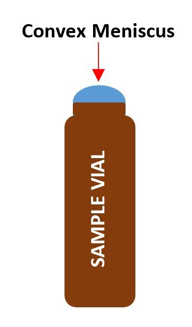
When filling volatiles samples, a convex meniscus must be formed over the mouth of the vial to eliminate the formation of air bubbles and headspace prior to capping.
Once the vial is capped, it should be inverted and gently tapped and observed for bubbles. If an air bubble appears in the vial, discard the sample and collect another. Bottles with bubbles should be discarded unless a new samples cannot be collected. The presence of the bubble should be noted in the field notes, field data sheets, and monitoring report.
Sediment
All groundwater samples should be free of any visible sediment. Therefore, the pump should not be allowed to touch or draw sediments from the bottom of the well.
Groundwater samples should not be field filtered to remove sediment.
Water Quality Parameter Stabilization
Water Quality Parameters are considered stable when three successive readings, collected 3-5 minutes apart, are within:
- ± 3% for temperature (minimum of ±0.2 degree Celsius [°C])
- ± 0.1 for pH
- ± 3% for conductivity
- ± 10 millivolts (mV) for redox potential
- ± 10% for dissolved oxygen
- ± 10% for turbidity (with a goal of less than 10 NTUs)
Monitoring Well Reference Points and Surveys
Reference Point
A surveyed reference mark should be placed on the top of the well casing and not on the protective casing or the well apron. The well casing is more stable than the protective casing or well apron and thus better for use as a measuring point.
The surveyed reference mark on the well casing also allows for the direct measurement of the depth to water and total depth of the well.
Survey Frequency and Accuracy
The Solid Waste Program recommends an annual survey to confirm the measuring point elevations for all monitoring wells at the landfill. If there are changes in the groundwater flow pattern/direction, or damage caused by freeze/thaw is noted then more frequent surveying may be required.
The monitoring wells should be surveyed vertically and horizontally. The location survey must achieve a horizontal accuracy of 1.0 foot and the elevation survey must achieve a vertical accuracy of 0.01 foot.
 Indicates an external site.